
Objective 1.4 — Reactive and Apparent Power#
LO# |
Description |
|---|---|
1.4 |
I can compute the reactive and apparent power values for an AC-powered circuit. |
By the end of this reading you should be able to:
Explain how capacitors and inductors shift the phase between voltage and current.
Distinguish real power \(P\), reactive power \(Q\), and apparent power \(S\), and give the correct unit for each.
Use the power triangle to relate the three, and compute power factor.
Explain what a low power factor actually costs — the current it forces, not the VARs themselves — and how power-factor correction removes that cost.
Beyond the Resistor#
Objective 1.3 dealt only with resistors, where voltage and current stay in phase and \(P = V_\text{rms}I_\text{rms}\) tells the whole story. Real systems are not that tidy. Motors have windings, cables have capacitance, and both introduce elements that store energy instead of consuming it.
A capacitor stores energy in an electric field. Current leads voltage by \(90^\circ\).
An inductor stores energy in a magnetic field. Current lags voltage by \(90^\circ\).
Over a full cycle, each of these takes energy from the source and then gives all of it back. Neither one consumes any net power.
Key Concept
Reactive elements borrow energy and return it; resistors keep it. But a borrowed ampere is still an ampere — it flows through the same generator, the same transformer, and the same copper as a useful one, and it heats them just the same.
Where the Power Goes#
When voltage and current are out of phase by an angle \(\phi = \phi_V - \phi_I\), only the component of current in phase with the voltage delivers energy. That fraction is \(\cos\phi\):
Check the two extremes:
\(\phi = 0^\circ\) (pure resistor) — \(\cos\phi = 1\), so all of the product does work.
\(\phi = \pm 90^\circ\) (pure capacitor or inductor) — \(\cos\phi = 0\), so none of it does.
Everything real falls between. The remainder is still flowing through the wires; it simply does not accomplish anything.
Three Kinds of Power#
Because the product \(V_\text{rms}I_\text{rms}\) splits into a useful part and a useless one, we give each a name — and, importantly, a different unit, so that a glance at the units tells you which quantity you are holding.
Quantity |
Symbol |
Formula |
Unit |
|---|---|---|---|
Real power |
\(P\) |
\(V_\text{rms}I_\text{rms}\cos\phi\) |
watts (W) |
Reactive power |
\(Q\) |
\(V_\text{rms}I_\text{rms}\sin\phi\) |
volt-amperes reactive (VAR) |
Apparent power |
\(S\) |
\(V_\text{rms}I_\text{rms}\) |
volt-amperes (VA) |
Real power is what does work and produces heat — the only one that shows up on an energy bill. Reactive power is the energy sloshing in and out of the fields each cycle. Apparent power is the total the source and the wiring must actually be built to carry.
The Power Triangle#
The three are not independent, and they do not add arithmetically. Because \(P\) depends on \(\cos\phi\) and \(Q\) on \(\sin\phi\), they are perpendicular components of \(S\):
The angle between \(S\) and \(P\) is the same \(\phi\) as between voltage and current, which gives the power factor:
Power factor runs from 0 to 1. A power factor of 1 means every volt-ampere the source supplies is doing useful work.
Key Concept
\(P\) and \(Q\) are the legs of a right triangle and \(S\) is the hypotenuse. A 3 kW load drawing 4 kVAR is 5 kVA, not 7. Adding them arithmetically is the single most common error on this objective.
You will also hear power factor described as lagging or leading:
Lagging — current lags voltage, so the load is inductive. Motors behave this way, and most industrial loads are lagging.
Leading — current leads voltage, so the load is capacitive. Long cable runs and correction capacitors behave this way.
Why Power Factor Costs Money#
Reactive power does no work, so it is tempting to ignore it. The utility does not — but the reason is more interesting than it first appears, and it is worth getting exactly right.
Here is the surprise: reactive power itself consumes zero net energy. Over each cycle, \(Q\) is energy flowing into the load’s magnetic or electric fields and then flowing straight back out again. It averages to nothing. Your home electric meter reads kW·h, which is real energy, so a homeowner running a badly reactive load pays nothing extra on that meter.
So if the VARs are free, what is the problem? The problem is the current they require. For a fixed real power and voltage,
Low power factor means more amperes for the same watts. And the amperes hurt, in three named ways:
\(I^2R\) losses upstream. Every extra ampere flows through the resistance of transmission lines, transformer windings, and building wiring, dissipating real power as heat along the way. That energy is genuinely consumed — just by the copper instead of by the load. Note the square: cutting the power factor in half doubles the current and quadruples the conduction loss.
Equipment capacity. Generators, transformers, cables, and switchgear are thermally limited by current, which is exactly why they are rated in VA, not W. A load at \(\text{pf} = 0.5\) ties up twice the transformer capacity of a unity-power-factor load drawing the same real power. Someone has to build and maintain that capacity.
Voltage regulation. Reactive current flowing through the reactance of the lines drops the voltage. On transmission lines, where reactance dominates resistance, \(Q\) is the main driver of voltage sag — and in the extreme, this mechanism is behind grid voltage collapse events.
Utilities know this well. Large industrial and commercial customers are billed with kVA demand charges or power-factor penalty clauses, which commonly kick in once the power factor drops below about 0.90 to 0.95. Residential customers are not, and that is exactly consistent with the physics: the meter on a house measures real energy only.
Key Concept
You pay for watts. You size the hardware for volt-amperes. The gap between the two is what power factor measures — and the payment shows up as copper losses, infrastructure capacity, and (for large customers) explicit utility penalties, never as VARs on an energy meter.
Nobody pays for the VARs. Everybody pays for the amperes the VARs require.
Power-Factor Correction#
Here is the satisfying payoff. The real villain is reactive current traveling long distances through resistive wire — and since \(Q\) can be generated anywhere, a lagging (inductive) load can be fixed without touching the load at all.
Place a capacitor bank right next to the inductive load. The capacitor supplies leading VARs that cancel the load’s lagging VARs, so the reactive current now circulates in a short local loop between the capacitor and the load instead of traversing the entire grid. From the utility’s point of view the combined load looks nearly resistive, \(\text{pf} \approx 1\), and the line current drops to nearly \(I = P/V\). This is exactly what those big gray capacitor banks bolted to poles and factory walls are doing.
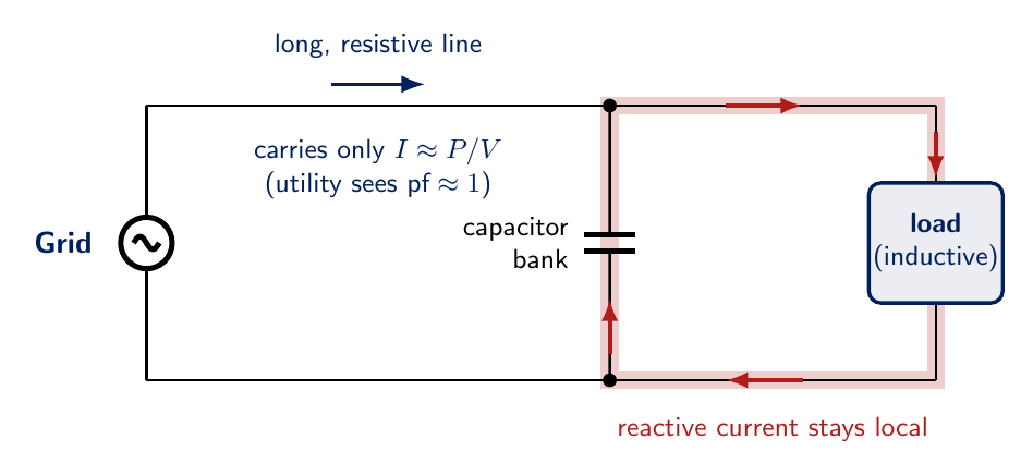
Note what did not change: the load still draws exactly the same \(Q\) it always did, and the capacitor still stores and returns energy the way capacitors do. What changed is where that reactive current flows. It no longer crosses the long, resistive line — so the \(I^2R\) losses fall, the line and transformer capacity is freed, and the voltage sag eases. All three harms are attacked by moving the same current a shorter distance.
Example Problem
A motor on a \(240\) V RMS, 60 Hz line draws \(15\) A RMS at a lagging power factor of 0.80. Find the apparent, real, and reactive power, and the phase angle.
Understand: The motor is an inductive load, so current lags voltage. We are given the two RMS terminal quantities and the power factor, which is all three legs of the triangle in disguise.
Identify Key Information:
Knowns: \(V_\text{rms} = 240\) V, \(I_\text{rms} = 15\) A, \(\text{pf} = 0.80\) lagging.
Unknowns: \(S\), \(P\), \(Q\), and \(\phi\).
Assumptions: Values given are RMS, as AC ratings always are unless stated otherwise.
Plan: Compute \(S\) first — it needs no angle. Then use the power factor to get \(P\), recover \(\phi\), and use it for \(Q\). Finally check the triangle closes.
Solve:
Check the triangle: \(\sqrt{2880^2 + 2160^2} = 3600\) VA. ✓
Answer: \(S = 3600\) VA, \(P = 2880\) W, \(Q = 2160\) VAR, \(\phi = 36.9^\circ\). The line carries 3600 VA in order to deliver 2880 W of useful work.
Type-along
An aircraft AC bus at \(115\) V RMS, 400 Hz supplies a load drawing \(20\) A RMS at a lagging power factor of 0.90.
Find \(S\), \(P\), \(Q\), and \(\phi\).
The generator is rated at \(2.5\) kVA. Can it carry this load?
If the power factor were corrected to 1.0 while delivering the same real power, what current would the bus carry?
Solution
1. \(S = (115)(20) = 2300\) VA. \(P = 2300(0.90) = 2070\) W. \(\phi = \cos^{-1}(0.90) = 25.8^\circ\), and taking the sine exactly rather than rounding through the angle, \(Q = 2300\sqrt{1 - 0.90^2} = 1002.55\), so \(Q = 1003\) VAR. Check: \(\sqrt{2070^2 + 1002.55^2} = 2300\) VA. ✓
2. Yes — \(2300\) VA is below the \(2500\) VA rating, but only by about 8%. That is a thin margin for a flight-critical bus.
3. At unity power factor, \(S = P = 2070\) VA, so \(I = 2070/115 = 18.0\) A, down from 20 A.
The same useful work is delivered with 10% less current, which means less \(I^2R\) loss in the wiring, cooler conductors, and more headroom on the generator. That is exactly why power factor correction exists.
Method: Solving an AC Power Problem#
Convert every given value to RMS.
Identify the phase angle \(\phi\) — either directly, or from the power factor via \(\phi = \cos^{-1}(\text{pf})\).
Compute \(S = V_\text{rms}I_\text{rms}\). It requires no angle, so it is always the easiest.
Get \(P = S\cos\phi\) and \(Q = S\sin\phi\).
Check that \(S^2 = P^2 + Q^2\).
Label every answer with its correct unit: W, VAR, or VA.
Wrap-Up#
Capacitors and inductors store and return energy rather than consuming it, so they draw current without doing work. That splits the product \(V_\text{rms}I_\text{rms}\) into real power \(P\) (W), which does the work, and reactive power \(Q\) (VAR), which does not — with apparent power \(S\) (VA) as the hypotenuse of the right triangle they form. The ratio \(P/S\) is the power factor, and the gap between what you use and what the hardware must carry is precisely what it measures.
Objective 1.5 turns to a related question: once power reaches a device, how much of it comes out the far side, and where does the rest go?