
✏️ HW 5#
📜 Instructions#
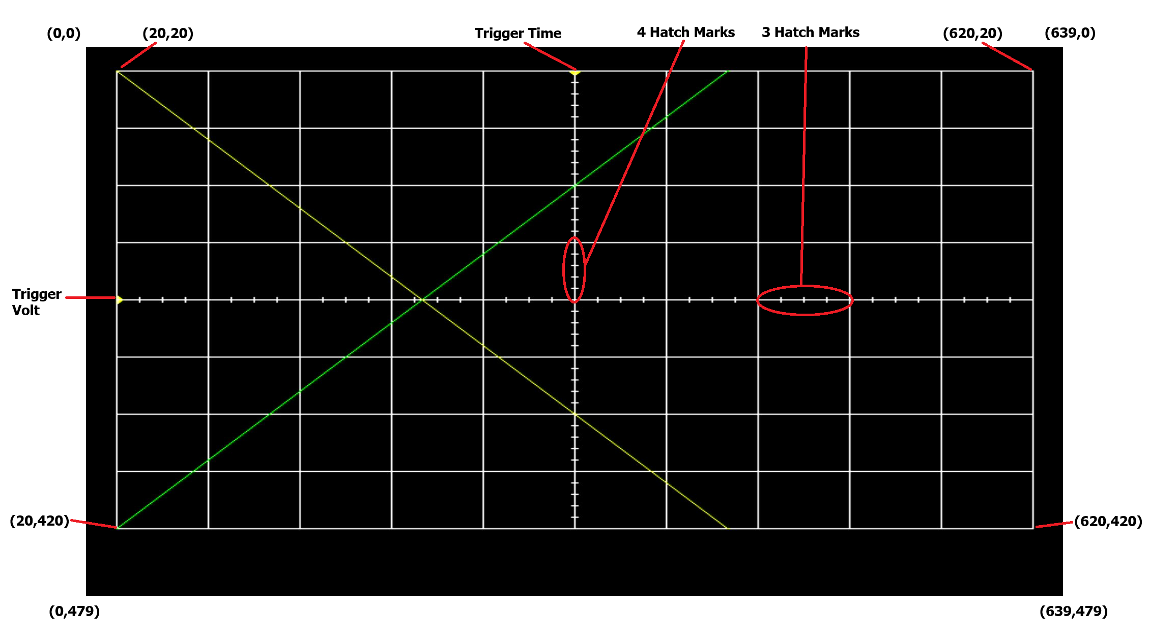
Draw a detailed diagram of the oscilloscope grid required for Lab1 [Do not try to reuse and edit the picture above]. A detailed diagram must be drawn on green engineering paper (or draw using a computer program) and include: – (x,y) corners of the monitor. – (x,y) each of the four major corners (already given), y-coordinates for all the major horizontal grid lines. – (x,y) coordinates for one set of three horizontal of hatch marks. Indicate with an arrow which set of three. – x-coordinates for all of the major vertical grid lines. – (x,y) coordinates for one set of four vertical of hatch marks. Indicate with an arrow which set of four.
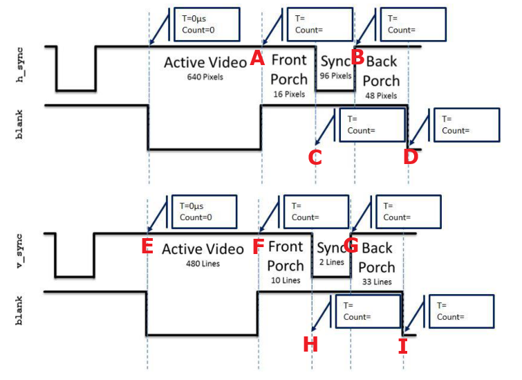
Given that the pixel clock is running at 25Mhz, add the durations and counts of the h_synch and v_synch signals show in Lab 1. Set time=0 on the blue dashed line on the left side of the region labeled “Active Video.” You should add durations and counts for all blue lines.
Deliverables#
Oscilloscope Grid Diagram
Timing Worksheet
Submit via gradescope