
🔬 Lab 3: Software Control of a Datapath#
📌 Objectives#
Students should implement a soft CPU in the fabric of the FPGA and use it to control a hardware datapath
📜 Synopsis#
In this lab, we will integrate the video display controller developed in Lab 2 with the MicroBlaze processor built using the fabric of the Artix-7 FPGA. In the preceding lectures, we learned about the Vivado and SDK tool chains, now it’s time to put that knowledge to the test by building a software controlled datapath. Lab 2 revealed some shortcomings of our oscilloscope that this lab intends on correcting. Specifically, we will add:
Using both trigger volt and trigger time for the trigger
Using polling and/or interrupts
The ability to enable and disable which channels are being displayed
The following figure shows required functionality - your program should allow the user to change the position of the triggerVolt and triggerTime indicators with the result that the waveform should be drawn so that the periodic waveform is increasing through that voltage at that time.
💻 Procedure#
Setup#
In order to accomplish this lab you will need to make some minor changes to the lab2 component, create a new custom IP, and then program that IP using the MicroBlaze, as described in the block diagram below. We will walk through these steps below.
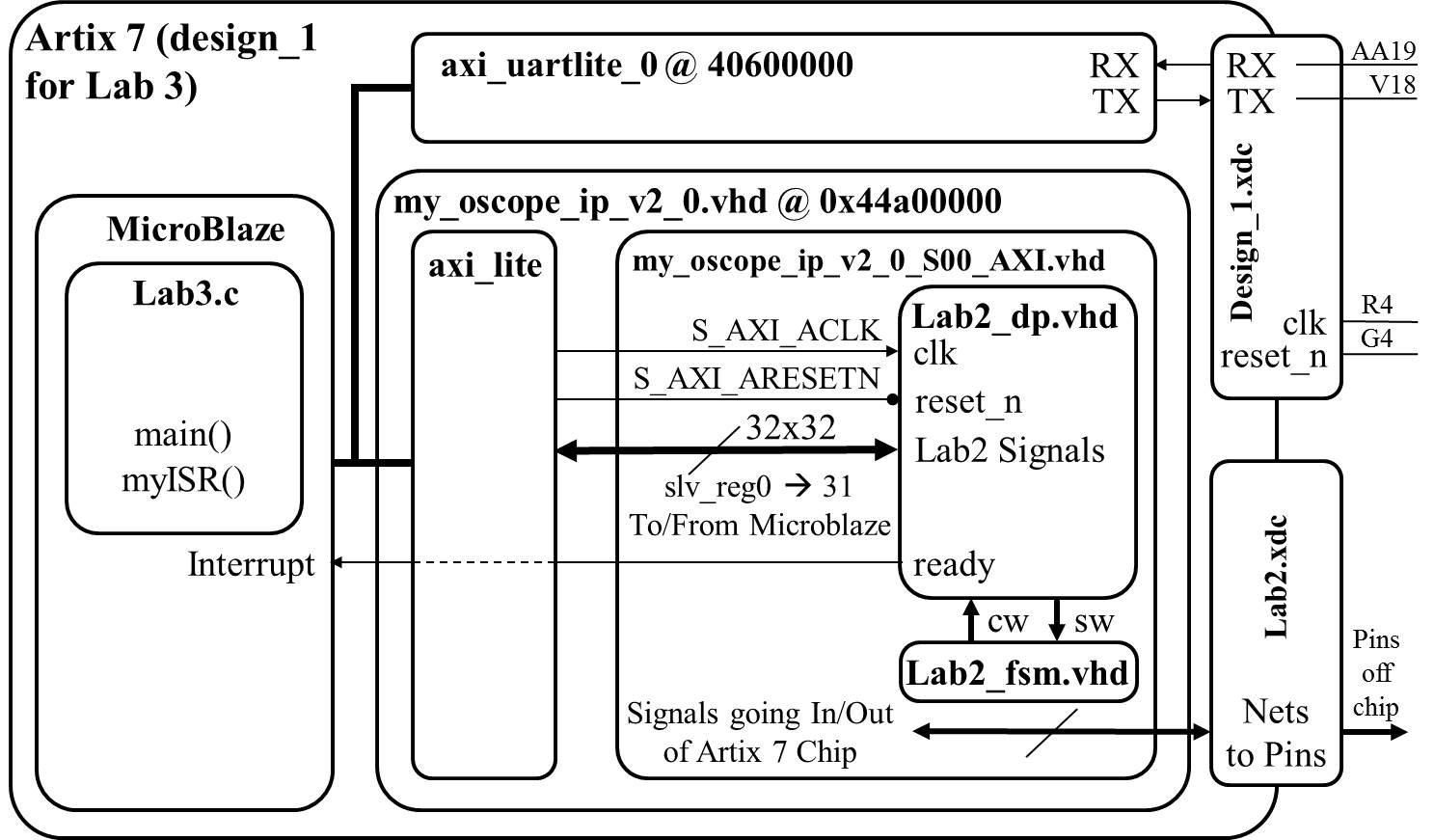
Note
Remember the Ready signal in the diagram above is coming from the Flag Register (FlagQ). It is assumed that you hooked the Ready signal coming from the Audio Codec into the “Set Flag” input to the Flag Register and the output of the Flag register FlagQ is the new “Ready” signal coming out of the lab2_dp, and eventually connecting toe Microblaze’s interrupt pin. If you accidentally skip the Flag Register and hook the audio codec’s Ready signal directly to the interrupt pin, you will find your system plots the sinusoid’s incorrectly, plotting what looks to be a very high frequency sinusoid instead of the correct frequency.
Note
If your Flag Register is 8-bits wide, you will need to extract the single bit of Q (the std_logic_vector output from the flag register) as the interrupt signal (the one set by the Ready signal). This may require you to extract the one bit Q as a separate signal to connect to the MicroBlaze in your block design.
💾 Lab Files#
Hardware#
Lab 3 will be setup similar to ICE 3. You will create a new microblaze project, create a custom IP which contains all of your Lab 2 datapath and control unit (and everything inside it), recreate your clock wizard clocks, connect the ready flag register to the interrupt pin, and pass any data needed through the slave registers. The ICE instructions will be helpful and the Lab 3 setup instructions from last year are here, in case you want them.
For the most part, your hardware you developed in lab2 will be unchanged. For controlling your TriggerVolt and TriggerTime, you can either (1) Retain your Lab2 buttons to control Trigger Volt and Trigger Time, but you must input these signals into Microblaze, and be able to display the values on the UART monitor or (2) Control TriggerVolt and TriggerTime from your Microblaze UART keyboard interface by using the slv_regs for microblaze to be able to write to TrigVolt and TrigTime into lab2 datapath ports
Hardware Setup#
Your first step will be to create a component for your lab2 component in your Vivado repository. This will require you to think about what signals are routed to the MicroBlaze and what signals are going outside the Artix 7 chip. The following table should help.
Signals To/From MicroBlaze |
Signals Going Outside Artix 7 |
|---|---|
exWrAddr |
clk |
exWen |
reset |
exSel |
ac_mclk |
L_bus_out, R_bus_out |
ac_adc_sdata |
exLbus, exRbus |
ac_dac_sdata |
flagQ |
ac_bclk |
flagClear |
ac_lrclk |
triggerTime |
sda |
triggerVolt |
scl |
ready |
tmds |
ch1_enb, ch2_enb? |
tmdsb |
For the mapping of the MicroBlaze slv_reg to/from lab2 ports, you need to specify not only which 32-bit slv_reg for each signal, but also which bits are used, and whether it is read/write (in or out to microblaze). Hint: use this spreadsheet: lab3_signal_mapping.xlsx
Implementation and Testing#
Lessons from previous years:
For all the lab2 signals you are reading into Microblaze AXI registers, add them to your C-code menu, using printf to print their values when you type the “?” command. This is very useful in debugging
Build your C-code incrementally, with baby-step tests such as these (and add each of these tests as one of your C-code menu options):
Draw a horizontal line on channel 1 and a diagonal line on channel 2, by writing the proper values to the BRAM (this test does not require your interface with the audio codec or the interrupt to work, and tests if you can write to the BRAM, and see the correct output on the scopeface)
pseudo code:
        case 'd':     // some of these will be XIL commands
            for (i=0;i<1024;i++) {
			   exWrAddr = i; // set BRAM address
			   exLBus = 185; // row for horz line
			                 // need to shift to upper 10bits?
			   exRBus = i;   // diagnonal line [need to shift?]
			   exWen = 1;    // write data to address in BRAM
			   exWen = 0;    // turn off write
            }
			break;
Or you could modify the above case ‘d’ to plot a sine wave, using a hardcoded sine wave look-up-table [this is only 64 samples so you would have to repeat it 16 times for 1024 samples]. Also, you need to scale these values to move to the upper 10-bits of the 16-bit values you write to the BRAM… like shift left 7, or multiply by 128.
u16 sinFunc[64] = {128,141,153,165,177,189,200,210,219,227,235,241,246,250,253,255,
255,254,252,248,244,238,231,223,214,205,194,183,171,159,147,134,
122,109, 97, 85, 73, 62, 51, 42, 33, 25, 18, 12,  8,  4,  2,  1,
1,  3,  6, 10, 15, 21, 29, 37, 46, 56, 67, 79, 91,103,115,128};
Use polling (polling the ready flag) to grab each sample and write them into your C-array. (This is a good test to see if you are getting the ready flag, able to read live samples, able to clear the flag, and repeat to fill your array)
pseudo code:
        case 'm':     // some of these will be XIL commands
            for (i=0;i<1024;i++) {
              while(flagQ==0){}; //wait on ready
              array_L[i] = LbusReg; // read audio values
              array_R[i] = RbusReg;
              ClearFlag = 1;   //clear the flag
              ClearFlag = 0;   //release the clear, so can be set again
            }
			break;
Use printf to print all the values in your array to the UART terminal (This is a good test to see if you are successfully reading audio codec samples in and storing them in your c arrary, or not)
        case 'p':
			for (i=0; i<1024; i++){
				printf("%x\r\n",array_L[i]);
			}
			break;
case ‘w’: Write your 1024 C-array samples (not triggered) to the BRAM (This is a good test to use, after you fill the array in the test case ‘m’ above, to see if you can write it to the BRAM and see it appear on scopeface… and fix any calibration issues)
case ‘t’: Given trig_volt, trig_time, and Array_L, write a command to search through the C-array to find the trigger point, and printf this location to the terminal
case ‘z’: Given this trigger location in the Array_L, write the appropriate data values in the Array_L to the BRAM, so the sine wave appears triggerd.
case ‘g’: Now you have all the pieces to create the “continuous” mode using polling and triggering
case ‘i’: Use interrupts (ISR) to fill the Array_L and Array_R with samples (Then use case ‘t’ and case ‘z’ above to write the arrays to BRAM)
case ‘c’: Now you have all the pieces to create the “continuous” mode with interrupts
Note on the “continuous” mode with interrupts using a linear buffer: Remember Main() and ISR() communicate with each other through global variables.
 Main() would set a global variable ARRAY_FULL = 0.
  Whenever the ISR() wakes up,
     It clears the flag ( 1 then 0),
     If ARRAY_FULL = 0, then
	   the ISR() saves the samples in the array,
	   increments the pointer for the next set of samples,
	   and eventually when this pointer = 1023,
	      the ISR() sets ARRAY_FULL = 1 and
		  resets the pointer to zero.
  Meanwhile, main() has been polling ARRAY_FULL waiting for it to be == 1.
     When it is, main() calls a function to look for the proper trigger location in the array,
	 and then another function to copy the correct 620 values in the array to the BRAMs based on the trigger location,
	 And then main() sets ARRAY_FULL=0,
	 and the ISR starts working again...
Lessons Learned the Hard Way in Previous Years#
Depending on your design, you will want to control some signals (like TrigVolt, TrigTime, Ch1_enb, Ch2_enb) from the UART keyboard Terminal while your program is running in continuous mode. (You will not want to halt the program in order to change these settings, but rather change them “live”). Therefore, in your C code “while loop”, you may want to check if the user has hit the key on the keyboard without having to actually read the key. For these cases, the command XUartLite_IsReceiveEmpty() will prove useful. Note that “uartRegAddr” is a constant, the address of the uart.
...
while(1) {   // run forever
	if (!XUartLite_IsReceiveEmpty(uartRegAddr)) {
    	c=XUartLite_RecvByte(uartRegAddr);
		switch(c) {
		  ...   // handle case for key press
		}  // end switch
	} // end if
	If (live_mode == 1) {
		Do live mode...
			grab samples from audio codec and put in Array;
			find trigger location in Array;
			Write 620 samples from Array to proper location in BRAM;
	} // end if
} // end while
Do NOT have polling FlagQ running at the same time as the ISR, as both would be attempting to clear the Flag, and you may find your system is missing samples, making the wave form plot appear to be a higher frequency than it actually is. One way to protect against this is to have all your polling cases disable interrupts with microblaze_disable_interrupts(), then microblaze_enable_interrupts() when you are done
pseudo code:
        case 'm':     // some of these will be XIL commands
		    microblaze_disable_interrupts();
            for (i=0;i<1024;i++) {
              while(flagQ==0){}; //wait on ready
              array_L[i] = LbusReg; // read audio values
              array_R[i] = RbusReg;
              ClearFlag = 1;   //clear the flag
              ClearFlag = 0;   //release the clear, so can be set again
            }
			microblaze_enable_interrupts();
			break;
When you are finding your trigger point in lab3, just like in lab2, you need to compare apples to apples. If your number in your C-array is 16-bits, it will be a large number in decimal like 26572, and this large 16-bit value you will want to write to your BRAM (as your VHDL code will later pull out the upper 10 or 9 bits) Meanwhile your triggerVolt is a small 10-bit number, like decimal 220. So to compare apples to apples in your C-code, (just for the purpose of finding the trigger) you might what to change the value in your C-array to the scale of the trigger volt by grabbing only its upper 10-bits (or in math, shift right 6 times, or divide by 2^6). Remember, in lab2 you probably also added (or subtracted?) an offset like the number like 34 (for the DC offset), so you would also need to add or subtract this from either trigvolt or the scale array number when you are doing the search for the trigger value.
Also, when doing your triggering math, make sure all your variables are declared as unsigned (like u16), not signed (like int), as the values are all unsigned and the comparisons will not work properly if declared as signed.
In the past, some students in their datapath hooked up L_Bus_out/R_Bus_Out directly to the 18-bit “signed” value coming out of the audio codec, not the 18-bit value converted to “unsigned”. If you do this, your sine wave will look strange (or maybe off the screen)… this can also impact your triggering. At some point, you need to convert from signed to unsigned. If you didn’t do this in your VHDL datapath, you could always do this in your C-code. If you are doing this conversion in C, remember you cannot just cast a variable from signed to unsigned. casting to unsigned in C would not do what you want (as we explained back in lab2). For example, if you have a signed value X = -7, and you cast X to an unsigned variable, what would -7 become? Unsigned values must be Zero or greater. -7 is undefined. If you go back to slide 11 in the lab2.pdf, you can see the pattern of this conversion with the 5 example numbers. It looks like all the lower bits stay the same, and only the MSB changes… it flips its value. I know two simple ways to flip the MSB (there are some other ways also), either (1) inverting the bit with a bitwise operator like XOR, or (2) adding a special number that keeps all the lower bits the same but only changes the MSB For method (2), adding the special number, look at the slide 11, you should be able to figure it out. For method (1), using XOR, ask yourself (a) what happens to a bit if I XOR it with ZERO?, and (b) what happens to a bit if I XOR it with ONE?
The XIL in and out functions are either 8-bit, 16-bit, or 32-bit [like Xil_Out16(exWraddr, i)], while you have some lab2 values that are different sizes (like trigvolt is 10-bits), so you may need to append bits in your VHDL code to make them match
Do not doing anything “slow” inside your ISR or while you are polling the samples into the array. Printf() is very slow. Also, writing your array_L values to the BRAM is very slow. So write your values from the Array_L to the BRAM in a different “for loop” than the route that grabs your samples from the audio codec into the Array_L. Along with this, you should make sure that new interrupt requests are not triggering while you’re serving the current interrupt.
🚚 Deliverables#
Gate Check 1 - Design#
[5 Points]
You need to decide if TrigVolt, TrigTime, Ch1_enb, and Ch2_enb will be controlled via buttons on the FGPA board or using the UART keyboard controlling them through Microblaze.
For this Gate Check you will turn in a revised Lab2_datapath block diagram, correctly showing all these signals (and their directions), and adding or removing parts (like button debouncing).
Also for this Gate Check, you will turn in a mapping of 32 AXI registers (slv_reg) to lab2 signals. or the mapping of the MicroBlaze slv_reg to/from lab2 ports, you need to specify not only which 32-bit slv_reg for each signal, but also which bits are used, and whether it is read/write (in or out to microblaze). Hint: use this spreadsheet: lab3_signal_mapping.xlsx
Push your code to your GitHub repository using git with the tag
Lab3_GC1
Gate Check 2 - Lab 2 with ExSel Off (‘0’)#
[5 Points]
You need to have all of your Lab 2 functionality implemented with the Microblaze. That is, you need to be able to set ExSel to ‘0’ from your microblaze C program (or via switch) and be able to achieve the same functionality as you did in Lab 2.
The demo can be live to your instructor or a video uploaded to Teams.
Push your code to your GitHub repository using git with the tag
Lab3_GC2
Gate Check 3 - CPU Interface#
[5 Points]
You need to be able to send UART commands using the terminal to your FPGA to adjust the trigger on the screen. The trigger on the screen should properly react to moving the trigger either up or down. Or, if you choose to not to control the trigger from the terminal and kept the lab 2 Trigger Volt and Time buttons, then show on your UART display that your C program can read the Trigger Volt and Trigger Time from the hardware buttons.
You need to implement at least one of the baby-step tests mentioned above in the “Implementation and Testing” section.
The demo can be live to your instructor or a video uploaded to Teams.
Push your code to your GitHub repository using git with the tag
Lab3_GC3
Required Functionality#
[40 Points]
In order to achieve required functionality, you will need to properly trigger the oscilloscope on channel 1 using a positive edge trigger. Control of this process is to be performed using the MicroBlaze. The main tasks of the MicroBlaze will include:
Move audio samples into a pair of linear or circular buffers. These circular buffers will be maintained in the address space of the MicroBlaze. That is, you should have two big arrays defined in your program. Use interrupts or polling of the ready bit through the flag register.
Examine the samples, looking for a trigger event.
Fill the remaining sample slots in memory.
Move the appropriate buffer values into the display memory of the oscilloscope (lab2) component.
Provide a user menu (through the terminal) allowing the user to adjust the trigger voltage and trigger time. (Or if you did not implement trigger control in C show that your MicroBlaze can read trigger volt and time by displaying on the UART monitor)
Your system must operate in continuous mode (not blocked waiting on user key-press)
For partial credit if the full system is not working, enumerate the test cases that do work (like case ‘m’)
The demo can be live to your instructor or a video uploaded to Teams.
Push your code to your GitHub repository using git with the tag
Lab3_ReqdFunc
A-level Functionality#
[10 Points]
Achieve required functionality.
Use the ready bit of the flag register to trigger an interrupt. The ISR should store the samples, look for a triggering event, and signal when the stored samples should be transfered to the BRAM in the oscilloscope component.
Add means to control Ch1_enb and Ch2_enb either by adding two FPGA board switches or controlled by MicroBlaze terminal interface.
The demo can be live to your instructor or a video uploaded to Teams.
Push your code to your GitHub repository using git with the tag
Lab3_AFunc
Turn In#
All of your work in this lab is to be submitted using Github and you will make submission in Gradescope to record the time each milestone is completed.
README#
[20 Points] For this lab, README only needs
Design: Updated lab2 block diagram with correct signals
Design: Mapping of 32 AXI registers to lab2 signals
Functionality
Evidence of completing Gate Checks 1 and 2, required functionality, and A-functionality, along with the date/time achieved. This section should clearly state for each milestone/functionality the date/time it was achieved, level of achievement (e.g, achieved, partially-achieved, not achieved), what was achieved, and how you proved it (via demo or evidence like images/videos). For example, you could have a table like this:
Milestone |
Date/Time |
What was achieved |
|---|---|---|
Gate Check 1 |
||
Gate Check 2 |
||
Gate Check 3 |
||
Required Functionality |
||
A Functionality |
Conclusion - Explain what your learned from this lab and what changes you would recommend in future years to this lab or the lectures leading up to this lab.
Grading#
Item |
Points |
|---|---|
Gate Check 1 |
5 |
Gate Check 2 |
5 |
Gate Check 3 |
5 |
Required Functionality |
40 |
A-Level Functionality |
10 |
Use of Git / GitHub |
5 |
Code Style |
10 |
README |
20 |
Total |
100 |