Lesson 5 – Circuits 3: Series and Parallel#
Learning Outcomes
Calculate the current, voltage, power, and equivalent resistance of any circuit with resistors both in series and parallel.
State the voltage and current relationship for resistors in series.
State the voltage and current relationship for resistors in parallel.
Be able to apply the voltage and current divider equations to calculate voltages or currents in circuits.
Describe the purpose of circuit protection.
Determine the required rating of a fuse or circuit breaker to protect a resistive circuit and whether or not a fuse of a certain rating would blow in that circuit.
Series and Parallel Circuits#
Last lesson we analyzed circuits containing two different configurations for connecting resistors, or devices that can be modelled as resistors, up to a voltage source. These configurations, known as series and parallel, were deliberately chosen because they represent fundamental ways of connecting devices. The vast majority of circuits we’ll encounter will place its components in either parallel or series (or both) arrangements.
Series Resistors#
Looking at the circuit below, we have a “series” arrangement. The resistors are connected end-to-end in a chain. Once those ends are connected to a voltage source, the same amount of current flows sequentially through each device, and each device is subjected to a fraction of the voltage. For a long string of lights, this is a way to apply a small voltage to each light, but a disadvantage is that one bad light will break the circuit, preventing current from flowing.

Fig. 1. A series circuit with one voltage source and three resistors.
Series Components
When only two components are connected at a node, those components are in series.
Analyzing the series circuit in Figure 1, starting with KVL for the one and only loop, we write:
Each voltage across a resistor can be rewritten using Ohm’s Law. Using KCL at each node, we can conclude that all current terms are equal — any number of resistors in series have the same current:
Substituting back into the KVL equation:
Series Equivalent Resistance
The current flowing through series components is always the same.
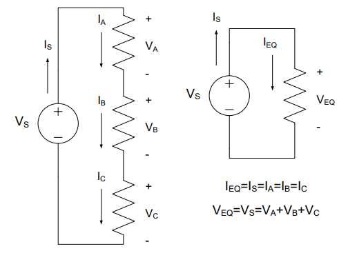
Fig. 2. A series circuit and its equivalent.
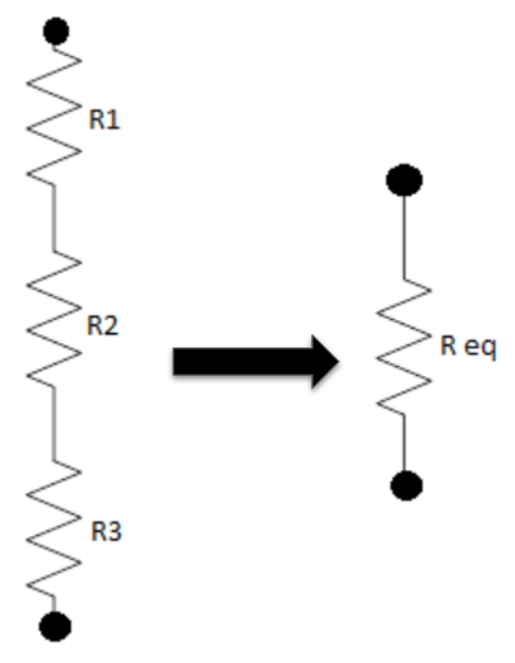
Fig. 3. Combining resistors in series into a single resistor.
At any location within a circuit, if we find two or more resistors in series, we can simplify them without even knowing the voltage or current. We can sum the resistances and rewrite that portion of the circuit as a single resistor. However, we must be careful that they are actually in series by verifying that there’s nothing else attached to the interior nodes. After all, those interior nodes will “disappear” when the resistors are replaced.
Example Problem 1
An inertial navigation system (INS) for a UAS is modeled as 4 resistors in series with a 28-Volt power supply. How much power is being produced by the power supply?
Understand: We have a number of devices (modeled as resistors) connected in series with a voltage source.
Identify Key Information:
Knowns: \(R_1\) = 100 Ω, \(R_2\) = 200 Ω, \(R_3\) = 300 Ω, \(R_4\) = 400 Ω; \(V_S\) = 28 V.
Unknowns: Power produced by the source, \(P_S\).
Assumptions: All power produced by the source is consumed by the load resistors.
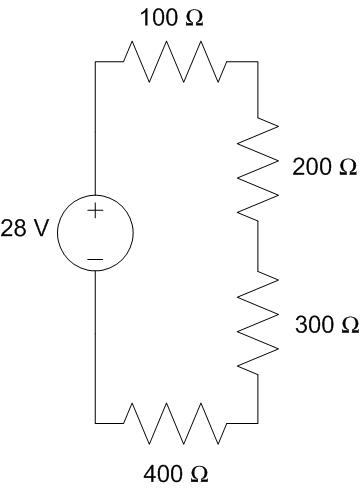
Fig. 4. Circuit for Example Problem 1: 28 V source connected to four series resistors (100 Ω, 200 Ω, 300 Ω, 400 Ω) modeling a UAS INS.
Plan: Consolidate the series resistors into a single equivalent resistor, then use the power equation.
Solve:
By KVL, \(V_{REQ}\) = \(V_S\) = 28 V.
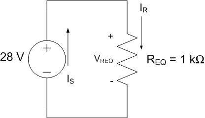
Fig. 5. Simplified equivalent circuit for Example Problem 1: 28 V source with a single 1 kΩ equivalent resistor.
Answer: 784 mW.
Example Problem 2
Two light bulbs are placed in series in the two circuits below and are each represented by resistors \(R_1\) and \(R_2\). The voltage source in both circuits remains the same, as well as the sum of the resistors. In Circuit #1, the resistors are equal, but for Circuit #2, they are different. For each circuit, how much power is consumed by each light bulb?
Understand: Two light bulbs are connected in series. We want to compare the power consumption as the resistances change between two different circuits.
Identify Key Information:
Knowns: \(V_S\) = 9 V. Circuit #1: \(R_1\) = \(R_2\) = 45 Ω. Circuit #2: \(R_1\) = 30 Ω, \(R_2\) = 60 Ω.
Unknowns: \(P_1\) and \(P_2\) for each circuit; current in the circuits.
Assumptions: The bulbs can be modeled as resistors.
Plan: Replace the two series resistors with a single equivalent resistor, then find the current, and compute the voltages and powers.
Solve:

Fig. 6. Circuit #1 for Example Problem 2: 9 V source with two equal 45 Ω resistors in series.
Circuit #1: \(R_{EQ,1} = 45\ \Omega + 45\ \Omega = 90\ \Omega\)
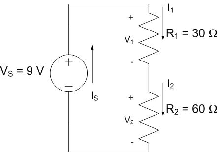
Fig. 7. Circuit #2 for Example Problem 2: 9 V source with unequal 30 Ω and 60 Ω resistors in series.
Circuit #2: \(R_{EQ,2} = 30\ \Omega + 60\ \Omega = 90\ \Omega\)
Both circuits have the same equivalent resistance of 90 Ω.

Fig. 8. Combined equivalent circuits for Example Problem 2: both Circuit #1 and Circuit #2 reduce to a 9 V source with a 90 Ω equivalent resistance.
Circuit #1 |
Circuit #2 |
|---|---|
\(V_{1} = (45\ \Omega)(100\ \text{mA}) = 4.5\ \text{V}\) |
\(V_{1} = (30\ \Omega)(100\ \text{mA}) = 3.0\ \text{V}\) |
\(V_{2} = (45\ \Omega)(100\ \text{mA}) = 4.5\ \text{V}\) |
\(V_{2} = (60\ \Omega)(100\ \text{mA}) = 6.0\ \text{V}\) |
\(P_{1} = (4.5\ \text{V})(100\ \text{mA}) = 450\ \text{mW}\) |
\(P_{1} = (3.0\ \text{V})(100\ \text{mA}) = 300\ \text{mW}\) |
\(P_{2} = (4.5\ \text{V})(100\ \text{mA}) = 450\ \text{mW}\) |
\(P_{2} = (6.0\ \text{V})(100\ \text{mA}) = 600\ \text{mW}\) |
Check: \(P_S = V_S I_S = (9\ \text{V})(100\ \text{mA}) = 900\ \text{mW}\) — matches the sum in each circuit. ✓
Answer: For Circuit #1, \(P_1 = 450\ \text{mW}\) and \(P_2 = 450\ \text{mW}\). For Circuit #2, \(P_1 = 300\ \text{mW}\) and \(P_2 = 600\ \text{mW}\).
Voltage Division#
For resistors in series, the respective voltages can be calculated using a shortcut known as voltage division. For a series resistor \(R_X\) with total voltage \(V_{Total}\) across the chain and equivalent resistance \(R_{EQ}\):
Voltage Divider
The voltage drop is proportional to the ratio of the resistances. Only works for resistors in series.
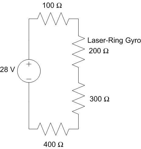
Fig. 9. Voltage divider illustration: the voltage across each series resistor is proportional to its resistance relative to the total equivalent resistance.
Example Problem 3
An inertial navigation system (INS) for a UAS is modeled as 4 resistors in series with a 28-Volt power supply. What is the voltage drop across the laser-ring gyro, which is modeled as a 200-Ω resistor?
Understand: Several resistors in series with a voltage source. We want the voltage across one resistor in the middle.
Identify Key Information:
Knowns: \(V_S\) = 28 V; R values are 100, 200, 300, and 400 Ω.
Unknowns: \(V_{200Ω}\).
Assumptions: None.
Plan: Use the voltage divider equation with \(R_X\) = 200 Ω.
Solve:
Answer: The voltage drop across the laser-ring gyro is 5.6 V.
Example Problem 4
You have two 150-Ω resistors and a third resistor of unknown value, all in series and subjected to a 6 V source. If 1 V is desired across this third unknown resistor (\(R_A\)), what should the value of \(R_A\) be?
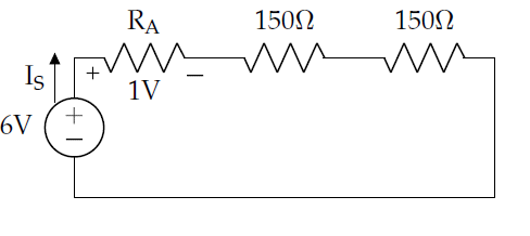
Fig. 10. Circuit for Example Problem 4: 6 V source with two 150 Ω resistors and an unknown resistor R_A in series.
Understand: Three resistors in series; find the resistance that will cause 1 V to drop across \(R_A\).
Identify Key Information:
Knowns: \(V_S\) = 6 V; the other two resistors are 150 Ω each; \(V_A\) = 1 V.
Unknowns: \(R_A\), \(I_S\).
Assumptions: None.
Plan: Combine the two 150 Ω resistors to 300 Ω equivalent. Use KVL to find the voltage across the 300 Ω equivalent (5 V). Rearrange the voltage divider equation to solve for \(R_{EQ}\), then subtract the 300 Ω portion to find \(R_A\).
Solve: By KVL, the voltage across the 300 Ω equivalent is \(6\ \text{V} - 1\ \text{V} = 5\ \text{V}\).
Rearranging the voltage divider with \(R_X\) = 300 Ω, \(V_X\) = 5 V, \(V_{Total}\) = 6 V:
Since \(R_{EQ} = 300\ \Omega + R_A = 360\ \Omega\), we get \(R_A = 60\ \Omega\).
Answer: A 60-Ω resistor will provide the needed 1 V.
Parallel Resistors#
The other basic arrangement of devices is to place them in parallel. Instead of the devices being connected end-to-end, each device shares the same two nodes. Figure 11 below shows three resistors and a voltage source connected in parallel.
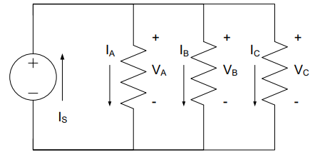
Fig. 11. A parallel circuit with one voltage source and three resistors.
When we apply KVL to this circuit, we find that all the voltage drops across all the resistors are the same:
This identity is the foundation of parallel equivalent resistance.
Inspecting either node with KCL, we find that:
Rearranging: \(V_S = R_{EQ(PARALLEL)} \cdot I_S\)
Parallel Equivalent Resistance
Devices in parallel have the same voltage drop across them. For two resistors only: \(\displaystyle R_{EQ} = \frac{R_X R_Y}{R_X + R_Y}\)
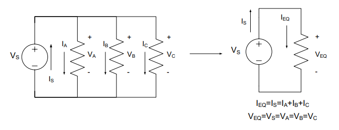
Fig. 12. A parallel circuit and its equivalent.
Example Problem 5
A cooling fan, which is modeled as a 30-Ω resistor, is powered by a 2.4-V battery. To monitor the battery, a voltmeter with a resistance of 660 kΩ is added in parallel as shown. How much resistance does the voltage source now see?
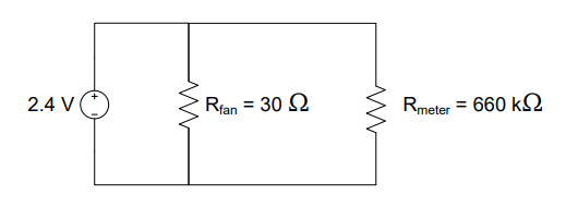
Fig. 13. Circuit for Example Problem 5: 2.4 V battery powering a 30 Ω cooling fan in parallel with a 660 kΩ voltmeter.
Understand: We are trying to simplify a circuit with two parallel resistors connected to a 2.4 V source. Since the voltmeter resistance is far larger than the fan resistance, the fan will dominate.
Identify Key Information:
Knowns: \(V_S\) = 2.4 V, \(R_{fan}\) = 30 Ω, \(R_{meter}\) = 660 kΩ.
Unknowns: \(R_{EQ}\).
Assumptions: None.
Plan: Use the two-resistor parallel equivalent resistance equation.
Solve:
Answer: The equivalent resistance of the circuit is 30 Ω.
Note: Because the voltmeter’s resistance is 22,000 times higher than the cooling fan’s resistance, the equivalent resistance is effectively the same as if there were no voltmeter. This is an important feature of monitoring equipment — it should not interfere with the circuit it monitors.
Example Problem 6
A voltage source that supplies 6 V is used to charge various cell phones connected in parallel. Two different types of phones are currently being charged, one modeled as a 120-Ω resistor and the other as a 60-Ω resistor. How much power does the voltage source provide?
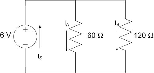
Fig. 14. Circuit for Example Problem 6: 6 V source charging two phones in parallel — 120 Ω and 60 Ω resistors.
Understand: We have a circuit with a 6-V source connected to two resistors in parallel.
Identify Key Information:
Knowns: \(V_S\) = 6 V, \(R_A\) = 60 Ω, \(R_B\) = 120 Ω.
Unknowns: Power \(P_S\) provided by the voltage source.
Assumptions: The source provides all the power needed by the load.
Plan: Find the equivalent resistance of the parallel resistors, then use \(P = V^2/R_{EQ}\).
Solve:
Notice the equivalent resistance is smaller than the smallest resistor value.
Answer: The power provided by the source is 900 mW.
Current Division#
For resistors in parallel, we can develop a KCL-based shortcut similar to the voltage divider. For parallel resistors where each has the same voltage \(V_{Total}\) = \(I_{Total}\) · \(R_{EQ}\):
Current Divider
For two resistors only: \(\displaystyle I_{X} = \frac{R_{Y}}{R_X + R_Y}I_{Total}\)
Current is inversely proportional to resistance — lower resistance gets more current. Only works for resistors in parallel.
Example Problem 7
In the circuit represented below, how much current passes through the 120-Ω resistor (\(I_B\))?
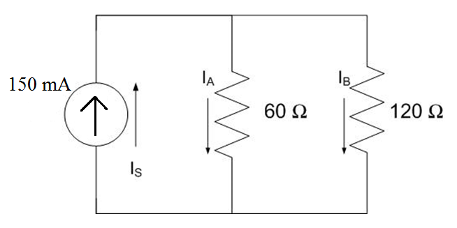
Fig. 15. Circuit for Example Problem 7: 150 mA current source with two resistors in parallel (60 Ω and 120 Ω).
Understand: Instead of the typical voltage source, here we have a current source providing a constant 150 mA. We have two resistors in parallel and want to find the current through one of them.
Identify Key Information:
Knowns: \(I_S\) = 150 mA, \(R_A\) = 60 Ω, \(R_B\) = 120 Ω.
Unknowns: \(I_A\) and \(I_B\).
Assumptions: None.
Plan: Use the two-resistor current divider equation.
Solve:
Answer: The current passing through the 120-Ω resistor is 50 mA.
Additionally, there is 100 mA of current passing through the 60-Ω resistor. Thus, where the resistors in parallel have a 1:2 ratio of resistance, their currents have a 2:1 ratio.
Voltage Adapters#
Oftentimes, in real life, we cannot control the source voltage, and our load may require a lower voltage. What do we do with the “extra” voltage (KVL tells us it has to go somewhere)? We can use what is called a voltage adapter. The adapter’s job is to “soak up” some of the voltage in the circuit, thereby reducing the voltage across a particular load to meet design criteria.
Example Problem 8
Determine the resistance required for a voltage adapter so that it can allow a 12-V lamp (modeled as a 2-kΩ load) to be used with an 18-V source. The voltage adapter is placed in series with the lamp, as shown below.
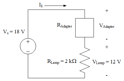
Fig. 16. Circuit for Example Problem 8: 18 V source with a series voltage adapter (R_Adapter) and a 2 kΩ lamp.
Understand: The lamp has a maximum voltage rating of 12 V. We need a voltage adapter to soak up the extra 6 V from the source.
Identify Key Information:
Knowns: \(V_S\) = 18 V, \(R_{Lamp}\) = 2 kΩ, \(V_{Lamp}\) = 12 V.
Unknowns: \(R_{Adapter}\) and \(V_{Adapter}\).
Assumptions: None.
Plan: Use Ohm’s Law with the lamp voltage and resistance to find the series current. Then use KVL to find \(V_{Adapter}\). Then use Ohm’s Law to find \(R_{Adapter}\).
Solve:
Since the circuit is series: \(I_S = I_{Adapter} = 6\ \text{mA}\).
Applying KVL:
Answer: A 1-kΩ resistor in series can serve as the voltage adapter.
If only 2-kΩ resistors were available, placing two 2-kΩ resistors in parallel would provide a 1-kΩ voltage adapter.
Fuses and Breakers#
Bad things can happen if we fail to keep electricity under control: equipment can be damaged; buildings can catch fire; and people can be injured, or even killed. Fortunately, using simple devices like fuses and circuit breakers can protect us and our circuits if something goes wrong.
A fuse is a very thin wire that allows current to flow normally. As current increases, the wire heats until it melts, severing the connection and stopping current flow. The highest current a fuse can handle without melting is its rating.
A circuit breaker has the same function as a fuse but doesn’t have to be replaced every time it “blows.” Most modern house and aircraft wiring use circuit breakers while most cars still use fuses.
A short circuit is a wire that connects the positive terminal of a voltage source directly to the negative terminal, causing a very large (theoretically infinite) current to flow. This can melt wires, start fires, and destroy electrical components.
Two rules for choosing fuse/breaker ratings:
The rating must be higher than the expected current in the circuit.
The rating must be lower than the failure point of the wiring.
In ECE 315: Calculate the maximum current, multiply by 1.1 (add 10%), then round up to the nearest whole or half number in the appropriate engineering notation units.
Example Problem 9
The internal circuitry of a battery powered camera is modeled as the resistive circuit below. What fuse rating would you choose to protect the circuit?
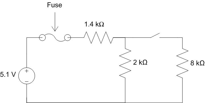
Fig. 17. Circuit for Example Problem 9: 5.1 V battery-powered camera modeled with 1.4 kΩ, 2 kΩ, and 8 kΩ resistors and a switch.
Understand: We must find the current drawn from the source. The circuit includes a switch that changes the equivalent resistance depending on whether it is open or closed. The fuse must handle the worst case (highest current).
Identify Key Information:
Knowns: \(V_S\) = 5.1 V; R values are 1.4 kΩ, 2 kΩ, and 8 kΩ.
Unknowns: Maximum current through the fuse; fuse rating.
Assumptions: Resistance in the wire is negligible.
Plan: Determine the current when the switch is open and when it is closed. The fuse rating is determined by the higher current case.
Solve:
Switch open (8 kΩ disconnected):
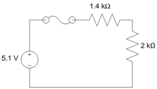
Fig. 18. Simplified camera circuit with switch open: 5.1 V source and 3.4 kΩ equivalent resistance (1.4 kΩ + 2 kΩ).
Switch closed (2 kΩ and 8 kΩ in parallel):
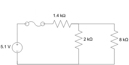
Fig. 19. Simplified camera circuit with switch closed: 2 kΩ and 8 kΩ combine to 1.6 kΩ in parallel, giving 3 kΩ total equivalent resistance.
The switch closed case draws the most current (1.7 mA). Multiplying by 1.1: \(1.7 \times 1.1 = 1.87\ \text{mA}\). Rounding up to the nearest whole milliamp gives 2 mA.
Answer: We would choose a fuse with a 2 mA rating to protect this circuit.
Key Takeaways#
Series Circuits. Resistors connected end-to-end (only two devices share each interior node) carry the same current; their equivalent resistance is the sum of all individual resistances.
Parallel Circuits. Resistors sharing the same two nodes all experience the same voltage drop; the equivalent resistance is found using the reciprocal-sum formula, and for two resistors the product-over-sum shortcut applies.
Voltage Divider. For series resistors, the voltage across one resistor equals its fraction of the total equivalent resistance multiplied by the total voltage; this is only valid for purely series connections.
Current Divider. For parallel resistors, the current through one branch is inversely proportional to its resistance relative to the equivalent resistance; lower resistance draws more current.
Voltage Adapters. A series resistor can absorb “extra” voltage from a source so that a load receives only the voltage it requires; the adapter resistance is determined from Ohm’s Law after finding the series current.
Fuses and Circuit Breakers. These protection devices interrupt excessive current before it can damage wiring or components; their rating must exceed normal operating current but stay below the wiring’s failure threshold.
Fuse Sizing Rule. In ECE 315, calculate the maximum operating current, multiply by 1.1 (add 10% headroom), then round up to the next available rating to select an appropriate fuse or breaker value.