Lesson 11 – Power Distribution#
Learning Outcomes
Explain how electrical buses provide voltage and current to all connected devices.
Given a power distribution system with AC and DC buses, calculate the required transformer turns ratio between electrical buses and determine appropriate values for circuit breaker protection.
Solve for the power provided by a source, the power consumed by various devices, the current at various points, and the efficiency of a power distribution system.
Power Distribution#
Power distribution is the process of getting power where it needs to go. It can involve getting electricity from a power plant to a community as we discussed in the previous lesson, or it can provide the appropriate power to every electrical component on an airplane.
As systems become more and more complex, trying to draw the circuit in the traditional way accurately can become both tedious and confusing. For this reason, engineers often use simple block diagrams to capture the essence of electronic systems.
Consider the following representation of a part of the T-52 electrical system in Figure 1:
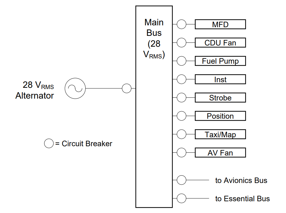
Fig. 1. The power bus of a T-52.
On the right of this diagram, we see eight components (MFD, CDU Fan, etc.) which require 28 \(V_{RMS}\) to operate. These items receive 28 \(V_{RMS}\) from the Main Bus which gets 28 \(V_{RMS}\) from the alternator. An alternator is a type of generator mostly used to generate power from automotive and other internal combustion engines. Notice, in the block diagram, the Main Bus also provides 28 \(V_{RMS}\) to two other buses, an Avionics Bus and an Essential Bus. Also notice how every device in the system, including the buses themselves, is protected by circuit breakers. This is just good engineering practice.
Electrical Buses
Electrical buses provide power to devices connected in parallel between the bus and a common ground.
All devices connected to a bus receive the same voltage.
A bus is simply a piece of metal or wiring which has a known voltage applied to it. To explain what this means, let’s look at the equivalent circuit diagram (Figure 2) for the same portion of the T-52 electrical system:
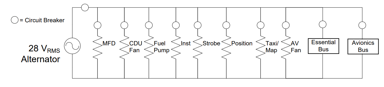
Fig. 2. The traditional circuit diagram for a T-52 electrical system.
It is important to realize both of the above diagrams are equivalent since they both convey the same amount of information about the electrical system. They just do it differently.
Since all of the devices (including the Essential and Avionics Buses) require the same voltage, we put everything in parallel with the voltage source (the 28 \(V_{RMS}\) alternator). Devices in parallel share the same voltage, and we want everything to share 28 \(V_{RMS}\). If we added anything else to the bus, it would also be added in parallel and would therefore get the full 28 \(V_{RMS}\) dropped across it. The bus itself is simply the upper node of the circuit, as in Figure 3:
Fig. 3. T-52 Circuit Diagram.
Many electrical systems, including our homes, will use a metal bar (Figure 4) to serve as a bus. Any device that is added to the bus is simply wired directly to this metal bar. As long as everything is wired in parallel, all devices get the expected voltage.
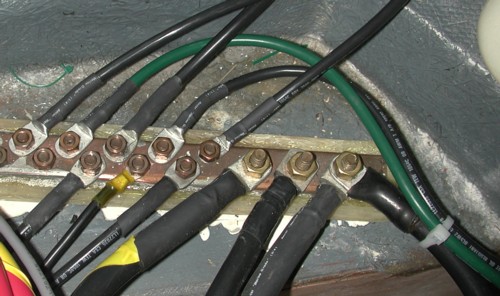
Fig. 4. Metal bar serving as a bus.
We often talk about a bus (or a node) as having a specific voltage, such as saying the T-52 Main Bus has a voltage of 28 \(V_{RMS}\). While this is very useful, it is not technically accurate. What we really mean is the voltage drop from the bus to a common ground is 28 \(V_{RMS}\). Just as a bus is a common node used to provide a common voltage to different devices, a common ground is also a common node used to return the current flow back to the source. In block diagrams, the common ground (which completes the circuit) is implied but not shown.
Most vehicles, such as cars and airplanes, actually use the metal frame of the vehicle to serve as a common ground. Therefore, adding electrical devices is as simple as running a wire from the appropriate bus to provide power, and then grounding the device to the metal frame to provide a return path back to the battery or generator.
If we define the common ground to be zero volts, then all other voltages can be given with respect to this value. Therefore, when we say the Main Bus has 28 \(V_{RMS}\), what we really mean is that it has a voltage that is 28 \(V_{RMS}\) higher than the common ground. This same principle is true with the electrical power we receive from our wall outlets — we get a voltage that is 120 \(V_{RMS}\) higher than the common ground running through our house.
Circuit Protection#
When designing an electrical distribution system, many will ask the question: “How many breakers do you need?” The answer varies greatly depending on what is being connected. For example, if you were designing an electrical system for an aircraft with numerous vital systems (such as flight controls, radar, communication systems, etc.) hooked to the same bus, putting one breaker on the front end of that bus would cause all systems to fail if the radar shorted out. Therefore, gauge the number and location of your breakers/fuses according to the design.
Another salient question is how to size the fuses and/or circuit breakers. A good heuristic is 10–15% above the max current draw. This gives the circuit some “headroom” to allow for small transient signals, while still protecting sensitive components. In the real world, fuses and breakers come in predefined ratings, so you would choose the closest appropriate value from the available fuses or breakers.
Example Problem 1
An aircraft power system is to be powered by a 190 \(V_{RMS}\) generator. Design the power distribution system for this airplane to meet the following requirements:
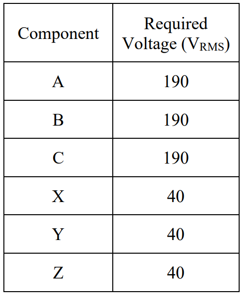
Fig. 6. Requirements table for Example Problem 1: devices A, B, C need 190 V_RMS; devices X, Y, Z need 40 V_RMS.
Understand: Since the requirements dictate two different voltages, we will need a transformer at some point in the design. Otherwise, we need to ensure each component is connected to the appropriate bus for its required voltage.
Identify Key Information:
Knowns: Generator voltage = 190 \(V_{RMS}\); required bus voltages = 190 \(V_{RMS}\) and 40 \(V_{RMS}\).
Unknowns: The system layout and the turns ratio for the transformer (a).
Assumptions: None.
Plan: Draw an initial block diagram, then calculate the turns ratio of the transformer based on the RMS values of the bus voltages.
Solve: Here is a preliminary block diagram of the required power distribution system:
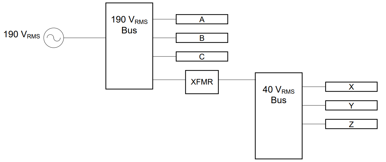
Fig. 7. Preliminary block diagram for Example Problem 1: 190 V_RMS generator → 190 V bus (devices A, B, C) → transformer (a = 4.75) → 40 V bus (devices X, Y, Z).
The 190 \(V_{RMS}\) bus receives power from the generator and distributes this power to devices A, B, and C, and also to a transformer. The transformer steps the voltage down to 40 \(V_{RMS}\) and sends the stepped-down voltage to the 40 \(V_{RMS}\) bus, which in turn provides power to devices X, Y, and Z.
The turns ratio of the transformer:
Answer: The aircraft power distribution system can be implemented as shown above, where the transformer has a turns ratio of a = 4.75.
Although that seems straightforward, we haven’t talked about current draws and power dissipation for these systems. Since the components are all connected in parallel, analyzing current draws and power dissipation is relatively simple. The current provided by the source (entering the common bus node) equals the sum of the currents drawn by individual devices (exiting the common bus node). Also, since we have assumed there are no power losses in the lines, the power the source must deliver equals the sum of the power dissipated by the individual components.
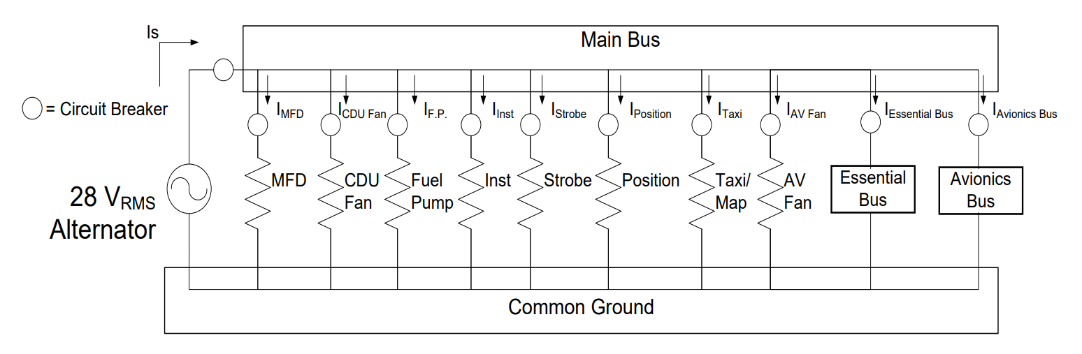
Fig. 5. T-52 bus example.
Example Problem 2
Add circuit protection to the following aircraft power system given the following component current draws. Also, calculate how much power the generator must provide to drive all of the components on the two buses.
Device |
Voltage (\(V_{RMS}\)) |
Current (\(A_{RMS}\)) |
|---|---|---|
A |
190 |
3 |
B |
190 |
8 |
C |
190 |
3 |
X |
40 |
10 |
Y |
40 |
4 |
Z |
40 |
5 |
Fig. 8. Starting block diagram for Example Problem 2: 190 V_RMS generator powering two buses with current draws for all devices.
Understand: The key to circuit protection is to figure out the flow of currents in the system. Since a bus is the same as a node, the total current flowing into the bus equals the total current flowing out of it.
Identify Key Information:
Knowns: Voltages and currents for all loads, transformer turns ratio a = 4.75.
Unknowns: Total current draw of the generator, power supplied, and circuit breaker locations/ratings.
Assumptions: None.
Plan: Determine the current flow through each bus using KCL, starting with the 40 \(V_{RMS}\) bus. Use the turns ratio to find the current drawn from the 190 \(V_{RMS}\) bus by the transformer. Sum all currents at the 190 \(V_{RMS}\) bus to find \(I_S\). Then calculate total power.
Solve: Apply KCL at the 40 \(V_{RMS}\) bus:
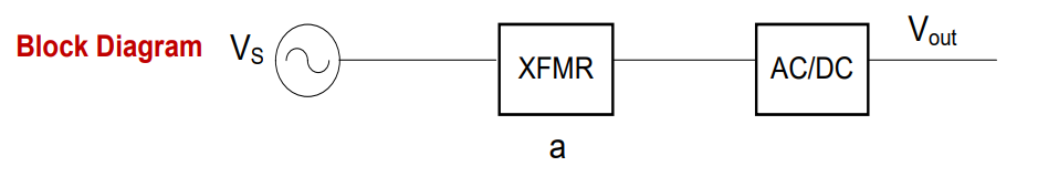
Fig. 9. KCL at the 40 V_RMS bus for Example Problem 2: total current I_2 = 19 A_RMS from transformer secondary.
Use the turns ratio to find the current drawn from the 190 \(V_{RMS}\) bus by the transformer:
The transformer steps voltage down from 190 \(V_{RMS}\) to 40 \(V_{RMS}\) and steps current up from 4 \(A_{RMS}\) to 19 \(A_{RMS}\). Now apply KCL at the 190 \(V_{RMS}\) bus:
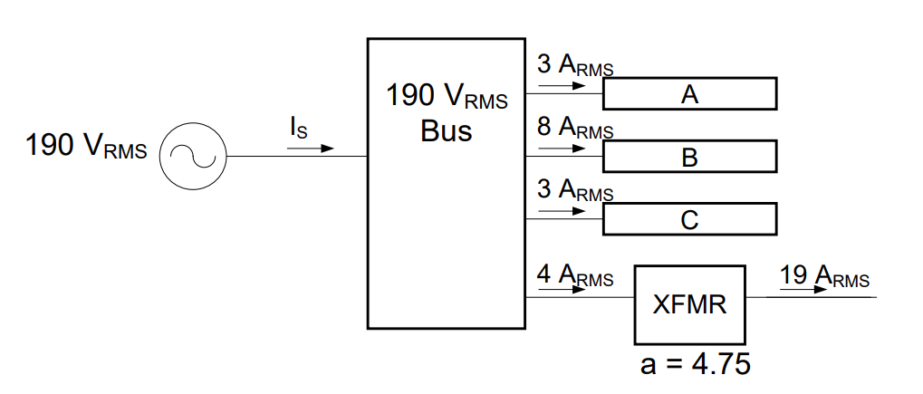
Fig. 10. KCL at the 190 V_RMS bus for Example Problem 2: generator must supply 18 A_RMS to devices A, B, C, and the transformer.
With all currents known, add circuit protection:
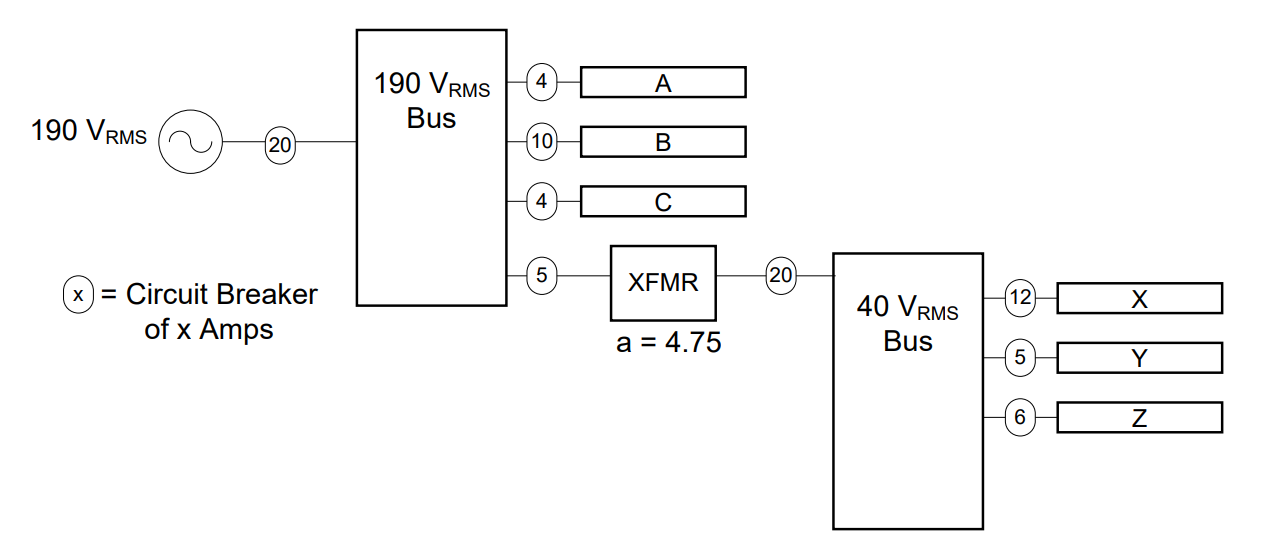
Fig. 11. Completed circuit protection design for Example Problem 2: circuit breakers added at the generator, each bus, and each device.
Calculate the total power supplied by the generator:
Answer: The power distribution system with circuit protection as shown must provide 3.42 kW of power.
Example Problem 3
An aircraft electrical system consists of a 160 \(V_{RMS}\) Bus and a 28 \(V_{DC}\) Bus, as shown. Calculate the turns ratio of the transformer and pick acceptable values for the circuit breakers labeled A and B. Assume the Comm and Camera each draw 3 A. The AC-to-DC converter is 90% efficient.
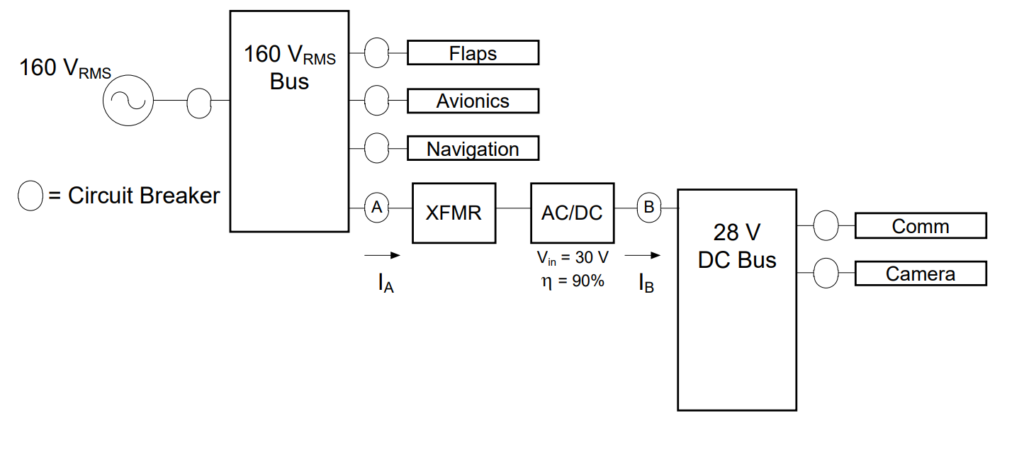
Fig. 12. Block diagram for Example Problem 3: 160 V_RMS bus → transformer → AC/DC converter (90% efficient) → 28 V_DC bus with Comm and Camera.
Understand: This example considers the scenario where a DC Bus is required. We will need to solve for power to figure out circuit breaker A.
Identify Key Information:
Knowns: Comm and Camera each draw 3 A at 28 \(V_{DC}\); AC/DC input = 30 \(V_{peak}\); 160 \(V_{RMS}\) bus; \(\eta_{ADC}\) = 90%.
Unknowns: Circuit breaker values (A and B), transformer turns ratio.
Assumptions: None.
Plan: This consists of three separate problems. First, find breaker B current using KCL. Second, find the turns ratio using the transformer voltages. Third, use the efficiency equation and power equation to find the current through breaker A.
Solve: Apply KCL at the DC Bus for breaker B:
Pick a circuit breaker rating slightly above 6 A → 8 A circuit breaker for B.
Next, find the turns ratio. The ADC requires 30 V as its peak input. Convert to RMS for consistency with the 160 \(V_{RMS}\) bus:

Fig. 13. Transformer turns ratio calculation for Example Problem 3: 160 V_RMS primary, 21.21 V_RMS secondary (30 V peak input to ADC).
Finally, find the current through breaker A. Start at the load and work backwards. Power consumed by the DC bus equipment:
Fig. 14. Power flow for Example Problem 3: 28 V_DC bus supplies 168 W total; ADC input is 186.7 W; circuit breaker A carries 1.167 A_RMS.
This is \(P_{out}\) of the ADC. Use the efficiency equation to find \(P_{in}\):
Since the transformer is ideal, the 160 \(V_{RMS}\) bus provides 186.7 W to this branch. Use the power equation to find \(I_A\):
Pick a circuit breaker rating slightly above 1.167 A → 1.5 A circuit breaker for A.
Answer: The transformer turns ratio is a = 7.544. Circuit breaker A = 1.5 A, circuit breaker B = 8 A.
Key Takeaways#
Electrical Buses. A bus is a common conductor (wire or metal bar) held at a known voltage; every device wired to a bus is connected in parallel with the source, so all devices on the same bus receive the same voltage.
Common Ground. A common ground (often the metal frame of a vehicle) provides the return current path for all devices and defines the 0 V reference from which bus voltages are measured.
Block Diagrams for Power Systems. Block diagrams replace complex circuit schematics with labeled blocks representing generators, transformers, ADCs, buses, and loads, making system-level design easier to understand and communicate.
Circuit Breaker Sizing. Breakers and fuses protect circuits by interrupting excessive current; a good rule of thumb is to rate them 10–15% above the expected maximum current draw, then choose the nearest available rating above that value.
KCL Applied to Buses. Because a bus is a node, KCL applies directly: the total current entering the bus from the source equals the sum of the currents drawn by all connected devices.
Multi-Voltage Systems. When devices require different voltages, a transformer steps one bus voltage to another; the transformer’s turns ratio is set by the ratio of the two required bus voltages.
Working Backwards from Load to Source. In multi-stage systems (bus → transformer → ADC → DC bus), efficiency and power are calculated starting from the load and working back through each stage to determine what the generator must supply.