Lesson 10 – AC-to-DC Conversion#
Learning Outcomes
Describe the four steps in the AC-to-DC conversion process.
Articulate how a diode and capacitor function in AC-to-DC conversion.
Given the efficiency and voltage specifications for an AC-to-DC converter, calculate the power supplied by the AC source and the power lost through the AC-to-DC converter.
AC-to-DC Conversion#
Although transformers make it more efficient to transmit AC power over long distances, many devices require DC power to operate. Computers, for instance, need DC power to run all of the data processing circuitry that makes a computer useful. Even though we plug them directly into our wall outlets, they actually have built-in AC-to-DC Converters (ADC) to provide the necessary DC power. Furthermore, anything that runs off of battery power, such as cell phones or tablets, uses DC power. When we charge these devices, the charger converts an outlet’s 120 \(V_{RMS}\) signal into an appropriate DC signal. In this lesson, we will explain how ADCs work.
Basics of AC-to-DC Conversion#
The most basic AC-to-DC Converter is the half-wave rectifier. To understand how this type of converter works, we need to introduce two common electrical devices:
A diode is a semiconductor device that allows electricity to flow in only one direction. The light-emitting diode (LED) is the most commonly seen diode, but electrical engineers use diodes for many other applications. This device is basically a “one-way” valve for current to flow through. We can use a diode to convert an alternating signal into one that is ALWAYS positive (a process called rectification). This process is needed in AC-to-DC conversion.
A capacitor is a storage device that acts like a temporary battery. If a voltage is present across the capacitor, it will charge up to that voltage. If the voltage is taken away, it will discharge if connected to a load. It is important to know that this charging and discharging does not happen instantaneously. For this reason, capacitors can be used to smooth the rectified signal.
Let’s take a close look at a general AC signal, starting at time t = 0 sec, and consider what is really going on with this signal.
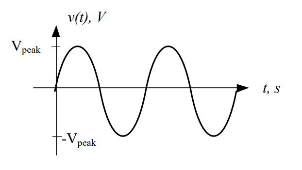
Fig. 1. Voltage of a general AC signal.
We can think of the voltage as a pushing force that causes electrons to move. When we first start on the graph at 0 ms, the pushing force of the signal is at 0 V. As time passes, however, this pushing force begins to increase until it reaches its peak voltage. As time passes even further, the pushing force decreases until it reaches 0 V, then turns negative and continues to decrease until it reaches its minimum. At this point, it starts increasing until it returns to its peak voltage.
Now think about the current this changing voltage would produce. When the voltage is positive, the pushing force pushes electrons through the circuit in one direction. When the voltage is negative, however, it becomes a negative pushing force, which pulls the electrons the other way. Push, pull. Push, pull. Push, pull.
Fig. 2. Current of a general AC signal.
That’s why it is called an alternating current: it spends half the time flowing forward and the other half flowing back.
Key Point: Negative currents are just currents flowing in the opposite direction than expected, and negative voltages are just voltages that are opposite of the polarity shown on the device.
What would happen if we allowed this signal to pass through a diode, which only allows current to flow in one direction? As Figure 3 below shows, the diode blocks the negative part of the signal from passing through, but lets the positive part continue. This occurs for both the voltage and the current.
Fig. 3. Voltage of a general AC signal before (left) and after (right) passing through a diode.
Even though the signal coming out of the diode is not a DC signal, we’ve gotten rid of all the negative voltages, which means we’re one step closer. Instead of push, pull, the signal is now push, pause, push, pause. The signal is now said to be rectified, and more specifically, we can say the signal is half-wave rectified because only half of the waveform is allowed to pass. This is where we get the term half-wave rectifier.
The key is understanding that the signal at the input of the diode has an average voltage over time of 0 V, while the output signal has an average voltage over time greater than 0 V.
Now that we know how the diode affects the signal, let’s look at the effects of the capacitor and its contribution to the resultant signal. When adding the capacitor to the half-wave rectifier, the capacitor must be placed in series with the diode and voltage source, as shown in Figure 4.
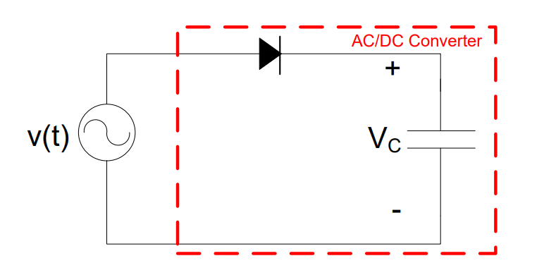
Fig. 4. A half-wave rectifier without a load.
A capacitor acts as a temporary battery. At “t1” ms in Figure 5, the output of the diode (shown as the dashed line) is at its peak. This voltage quickly charges the capacitor to the same value. Since no power is being consumed by the circuit, the output — represented by the solid line — remains constant. Interestingly, capacitors do not consume power, but rather, they store power in electric fields. The specifics of this will be covered in more detail in Lesson 15.
Fig. 5. Voltage of a rectified signal (dashed line) and capacitor voltage (solid line).
In this ideal case, where the ADC is not supplying power to anything:
Now, in order to supply power to a load, we need to place the load (\(R_{Load}\)) on the output of the ADC. We do this by placing that load in parallel with the capacitor, thereby ensuring that the load gets the same voltage as the capacitor. This is shown in Figure 6. It is important to note that \(R_{Load}\) is not actually part of the ADC. Instead, it is the tablet, cell phone, or computer that uses the DC power that is created.
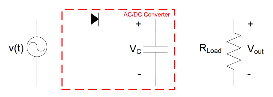
Fig. 6. A half-wave rectifier with a load.
At “t1” ms in Figure 7, the output of the diode (shown as the dashed line) is at its peak. This voltage quickly charges the capacitor to the same value. When the output of the diode starts to drop off towards zero volts, the capacitor starts providing current to the load. This current pulls power from the capacitor, causing it to be consumed in the load. When this occurs, the voltage across the capacitor drops slightly, which means \(V_{out}\) also decreases. Next, the voltage from the diode reappears and climbs back towards its peak, charging the capacitor back up to \(V_{peak}\) and continuing the cycle. We call this variation in voltage over time a “ripple”. The resultant output in Figure 7 is not a perfect DC signal, but it’s reasonably close.
Fig. 7. Voltage of a rectified signal (dashed line) and output voltage over a load (solid line).
The rate at which the capacitor voltage decreases is determined by two things: the size of the capacitor (bigger is better) and the magnitude of \(R_{Load}\) (a smaller \(R_{Load}\) means the capacitor discharges faster). A bigger capacitor can store more power, and a smaller \(R_{Load}\) draws more current from the capacitor. The bottom line is the diode blocks negative current (creating a rectified voltage), and the capacitor smooths out the bumps.
AC-to-DC Conversion Steps#
Before we look at ADCs from a block diagram perspective, let’s look at the overall process. It typically takes four steps to convert an AC signal into the needed DC format:
The Four Steps of AC-to-DC Conversion
Transformation — Use a transformer to step the AC voltage up or down to the level needed by the converter. The output \(V_{DC}\) is related to the rectified \(V_{peak}\), so a transformer is used to get the correct \(V_{peak}\) input.
Rectification — Use a diode (half-wave) or diode bridge (full-wave) to eliminate the negative portion of the AC signal. This is where most of the conversion work is performed.
Smoothing — Use a capacitor to smooth out the rectified signal into a more consistent voltage that can be used by the DC-powered device.
Regulation — Use a voltage regulator to remove the remaining ripple and ensure a constant voltage level is provided to the DC-powered device. The regulator slightly reduces the DC output voltage but minimizes the effect of changing \(R_{Load}\).
Figure 8 below shows the different steps of the AC-to-DC conversion process.
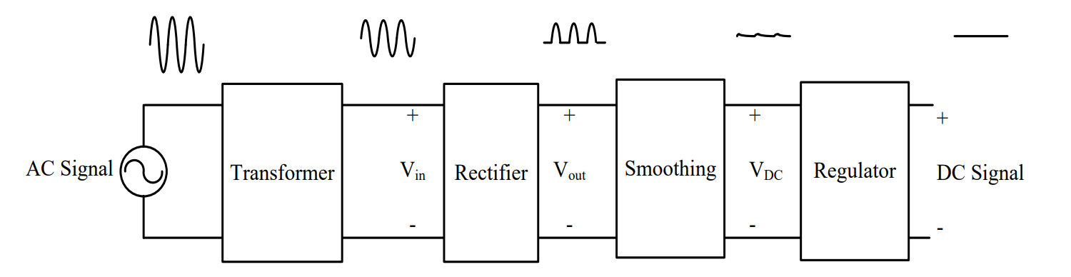
Fig. 8. The steps in the AC-to-DC conversion process.
For the rest of this lesson, this process will be displayed as a block diagram. The “XFMR” block will represent the transformation step, and an “AC/DC” block will represent rectification, smoothing, and regulation. If a half-wave rectifier and capacitor were used with a transformer in an ADC design, the design could be represented using a block diagram, schematic, or combination of both, as shown below. In this case, the ADC is in series with the transformer.
Fig. 9. Block diagram of AC-to-DC conversion process.
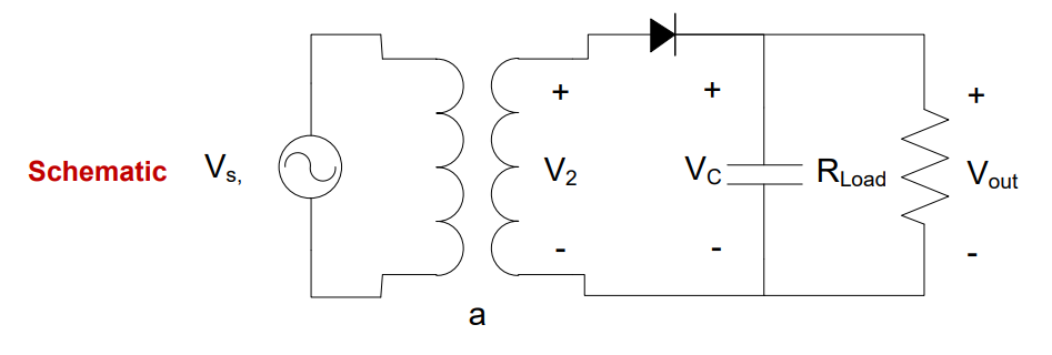
Fig. 10. Schematic of AC-to-DC conversion process.
Example Problem 1
The AC signal \(v(t) = 169.7\cos(360°\times 1k\cdot t)\ \text{V}\) is input into an ideal half-wave rectifier with a 10:1 turns ratio transformer. What is the DC output, neglecting the ripple?
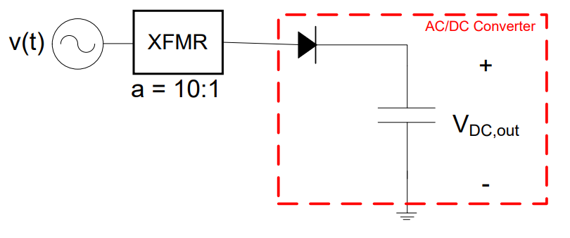
Fig. 11. Block diagram for Example Problem 1: AC source → transformer (a = 10) → ideal AC/DC converter → DC output.
Understand: We will need to step down the voltage before solving for our final DC output.
Identify Key Information:
Knowns: Input AC voltage amplitude = 169.7 V, turns ratio a = 10.
Unknowns: The output voltage, \(V_{DC,out}\).
Assumptions: We are dealing with an ideal transformer.
Plan: Use the turns ratio to determine the input voltage to the ADC. Since the converter is unloaded, the output voltage equals the peak of the input signal.
Solve: The input voltage is stepped down by the transformer:
Since the converter is unloaded, the DC voltage coming out of the converter is the peak voltage of the signal going into the converter:
Answer: The DC output from the AC-to-DC Converter is 16.97 V.
Example Problem 2
Assume the AC/DC block below is limited to the rectification, smoothing, and regulation stages, and the required input should be 8 V. Given a source voltage \(v_s(t) = 120\cos(360°\times 60\cdot t)\ \text{V}\), determine the turns ratio of the transformer to make the circuit work.
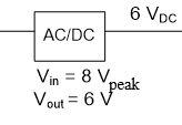
Fig. 12. Block diagram for Example Problem 2: 120 V source → transformer (a = ?) → AC/DC block (input 8 V, output 6 V_DC).
Understand: We need a transformer to step down the voltage. The ADC output is not quite equal to the peak input signal, which is a realistic scenario. We work backwards to decide what kind of transformer is needed.
Identify Key Information:
Knowns: Source voltage amplitude = 120 V, required ADC input = 8 V, ADC output = 6 \(V_{DC}\).
Unknowns: The turns ratio of the transformer.
Assumptions: Since the output voltage of the converter is less than the peak input, the ADC is not 100% efficient.
Plan: Draw the block diagram. The transformer must step the 120 V signal down to 8 V, which the ADC then converts to 6 \(V_{DC}\). Use the peak voltages to determine the turns ratio.

Fig. 13. Plan block diagram for Example Problem 2: transformer must step 120 V down to 8 V for the AC/DC converter.
Solve: Determine the turns ratio using the peak voltages:
Answer: A turns ratio of 15 is required. The design to convert \(120\cos(360°\times 60\cdot t)\ \text{V}\) to 6 \(V_{DC}\) is:
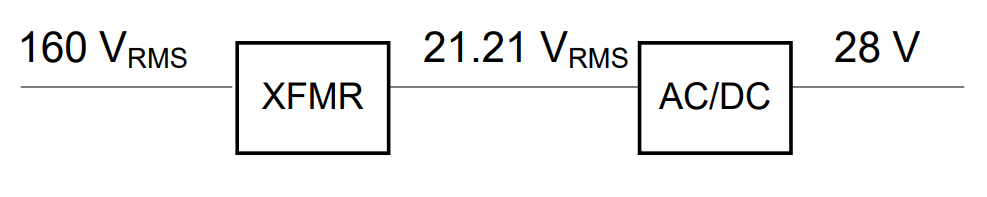
Fig. 14. Final design for Example Problem 2: transformer (a = 15) converts 120 V to 8 V; AC/DC block outputs 6 V_DC.
Example Problem 3
The ADC in the previous problem is used to power an electric drill, modeled as a 180-Ω resistor. If the ADC has an efficiency of 80%, how much power must the source provide?
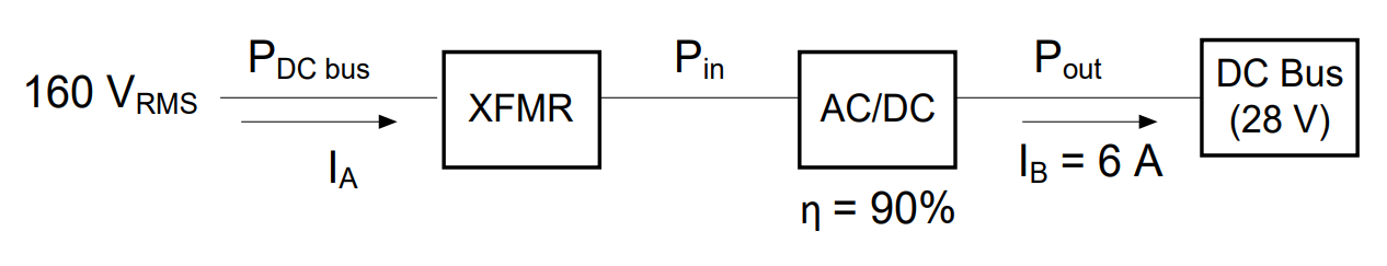
Fig. 15. Block diagram for Example Problem 3: transformer (a = 15) → AC/DC block (80% efficient) → 180 Ω electric drill.
Understand: Realistically, ADCs are not 100% efficient. We work backwards by first considering the power consumed by the drill and then accounting for the power lost in the ADC.
Identify Key Information:
Knowns: ADC output = 6 \(V_{DC}\), \(R_{drill}\) = 180 Ω, \(\eta_{ADC}\) = 80%, transformer is ideal.
Unknowns: Power provided by the source, \(P_S\).
Assumptions: The source supplies all power needed by the circuit. The transformer is ideal (100% efficient).
Plan: Calculate \(P_{drill}\) from the output voltage and resistance. Use the efficiency equation to find \(P_{in}\) to the ADC. Since the transformer is ideal, \(P_S\) = \(P_{in}\).
Solve: Model the entire ADC as a 6 \(V_{DC}\) source. The drill is in parallel with the capacitor, so \(V_{drill}\) = 6 V:
Fig. 16. Example Problem 3 solve step: AC/DC block modeled as a 6 V_DC source driving the 180 Ω drill.
This is the useful power. Now apply the efficiency equation to the ADC block:
Fig. 17. Efficiency calculation for Example Problem 3: applying the 80% efficiency equation to find the required AC/DC input power.
Since the transformer is 100% efficient: \(P_S\) = \(P_{in}\) = 250 mW.
Checking the full system power flow:

Fig. 18. Full power flow for Example Problem 3: source provides 250 mW → ideal transformer → 80% efficient ADC → 200 mW to the drill.
\(P_S\) = 250 mW → transformer (no loss) → ADC (loses 20%) → 200 mW to drill. ✓
Answer: The source must provide 250 mW.
Key Takeaways#
Why AC-to-DC Conversion is Needed. Most digital electronics and battery-powered devices require DC power, but the power grid delivers AC; every device plugged into a wall outlet relies on an AC-to-DC converter (ADC) internally or externally.
Diode (Rectification). A diode acts as a one-way valve that allows current to flow in only one direction; passing an AC signal through a diode eliminates the negative half of the waveform, producing a half-wave rectified signal.
Capacitor (Smoothing). A capacitor stores charge and acts as a temporary battery; when placed in parallel with the load, it maintains voltage during the gaps in the rectified signal and reduces the ripple.
Ripple. The small oscillation in output voltage caused by the capacitor charging and discharging is called ripple; larger capacitance and larger load resistance reduce the ripple.
The Four Steps of AC-to-DC Conversion. Transformation (scale AC voltage via transformer), Rectification (eliminate negative half-cycles with a diode), Smoothing (reduce ripple with a capacitor), and Regulation (remove remaining ripple with a voltage regulator).
Transformer in an ADC. A transformer is used before rectification to set the correct AC peak voltage, since the unloaded DC output of the converter approximately equals the peak of the rectified input signal.
ADC Efficiency. Real AC-to-DC converters are not 100% efficient; given an efficiency η, the required input power is \(P_{in} = P_{out}/\eta\), and this relationship is used to size the source and upstream components.