Lesson 20 – Analog-to-Digital Conversion 2#
Design signal conditioning between a transducer and an ADC to avoid aliasing, clipping, and a mismatch of dynamic ranges.
Calculate the bit rate of an ADC system and determine either how much memory is needed to store data for a specified duration of time or the duration of time the ADC will take to fill a memory card of a specified size.
Analog-to-Digital Conversion: Bit Rates and Signal Conditioning#
Bit Rates#
When we design systems that include ADCs, we often characterize them by how much data they provide per second; this is known as the ADC bit rate. It is relatively straightforward to calculate the bit rate – we take the number of bits produced by every sample (b) times the total number of samples per second, which is just the sampling frequency (fs):
Using the bit rate, we can begin to understand how much memory we will need to store a certain amount of data, or, conversely, how much data we can store on a certain amount of memory. Often, data rates (bit rates) are given in bits per second (bps) or kilobits per second (kbps), but data is measured in terms of Bytes (B). As a result, we will often need to convert between bits and Bytes, and we know that 8 bits is 1 Byte. However, with Bytes, instead of one kilobyte equaling 10^3^ Bytes, it is defined as 2^10^ Bytes. The most common conversions are:
Signal Conditioning#
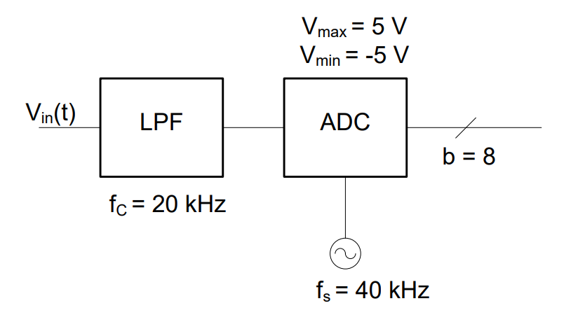
Typically, ADCs come with fixed sampling frequency, dynamic range, and resolution. Therefore, to ensure we avoid aliasing and clipping we have to condition our signal. For example, consider the 8-bit ADC below, which is used in a cheap voice recorder to convert the voltage signal from the microphone. The microphone outputs range from -10 mV to 10 mV.

Figure 1: 8-bit ADC with 40 kHz sampling rate
The ADC above uses a set sampling frequency and voltage limits. At a minimum, we must be sure to avoid aliasing. Aliasing is caused when the sampling rate is smaller than the Nyquist rate.
Up to this point, if we wanted to prevent aliasing, we simply picked an ADC with a sufficiently large sampling frequency. In this problem, and many real world problems, however, we are given the sampling frequency of a certain ADC. Additionally, the ADC also has a large voltage range when compared to our input signal. Therefore, we will also need to make sure the dynamic range of the input signal and the ADC are well aligned.
We start by checking for aliasing. The Nyquist criteria is:
Since we already know that fS = 40 kHz, we can use the Nyquist equation to solve for fHigh:
Therefore, in order to prevent aliasing, we need make sure the highest frequency in the input signal is less than 20 kHz. In this situation, we can prevent aliasing in one of two ways:
Increase the sampling frequency or
Decrease the highest frequency in the input with a low pass filter
Since aliasing is such a serious problem, it is common practice to add a low pass filter to the signal chain before an ADC. The cutoff frequency, fc, of the LPF is based on the ADC’s sampling rate, even if we know the frequencies in the input signal will never violate the Nyquist criteria.

Figure 2: Anti-Aliasing filter used with an 8-bit ADC
Now that we have ensured aliasing won’t be a problem, let’s examine whether the result will be accurate enough and specifically, let’s concentrate on our ability to resolve changes in the signal’s magnitude. First, let’s calculate the ADC’s resolution:
Recall that the dynamic range of the microphone, which is the input to the ADC, is -10mV to 10mV. Therefore, the entire range of the microphone’s output falls into a single level on the ADC. Under these circumstances, no matter what the output of the microphone is, it looks like a single value to the ADC. This problem has two potential solutions:
Reducing the ADC’s dynamic range (by bringing \(V_{\max}\) and \(V_{\min}\) closer together)
Adding more bits to the ADC’s output so you have more levels
Both the dynamic range of the ADC and the number of output bits are fixed, so neither one of these options would work. Instead, it is possible to use a transducer interface to match the dynamic range of the microphone output to the dynamic input range of the ADC. In this case, both dynamic ranges are symmetric around the t=0 axis, so we only need an amplifier with gain:
Now, we have the following block diagram:

Figure 3: Transducer and anti-aliasing filter used with an 8-bit ADC
Note - if the dynamic range of the microphone were to exceed that of the ADC, the ADC would simply assign the highest value in its range. However, this results in a significant loss of information and is called clipping. By properly designing a transducer interface to match the dynamic range of the input device and the ADC, we avoid two pitfalls:
No clipping occurs, and also
We make use of the entire dynamic range of the ADC (which is what the current problem details)
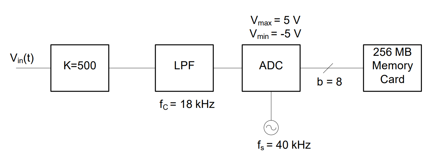
Finally, all the data produced by the ADC must be saved, but how much memory do we need? The ADC is producing 40,000 (because fs = 40kHz) 8-bit samples every second. Calculating the bit rate of this ADC is straightforward:
This means that over an hour, we’ll need to save:
And, since we want to express our answer in proper engineering units, the total memory is converted to Megabytes:
In conclusion, our voice recorder can store an hour’s worth of data in a relatively small memory card. Memory cards come in sizes measured in powers of 2, a 256 MB card is sufficient.

Figure 4: Signal conditioning and memory unit being used with an ADC
Example Problem 1#
An accelerometer is used to measure the G loading on an aircraft. The signal from the accelerometer is passed through an amplifier with a gain of 1,000, then filtered to prevent aliasing, and then sent through an ADC to be digitized. The digitized signal is then stored in a 512 MB Flight Data Recorder (FDR).

At three different times, the accelerometer outputs 490 μV, 7.8 mV, and -2.4 mV. What voltage will be entering the ADC at each of these times, and are there any problems with these voltages? In addition, how long will it take this system to fill the flight data recorder?
Understand: This is a complete signal chain for digitization of data from the accelerometer. The amplifier ensures the dynamic range of the accelerometer and the ADC are matched, while the LPF ensures any signal entering the ADC will be properly sampled, according to the Nyquist criteria. Our task is to make sure this signal chain has been properly designed and look for the two key pitfalls of ADC: aliasing and clipping. Also, we need to calculate the time it will take this system to fill the 512 MB memory card in the FDR.
Identify Key Information:
Knowns: We know the sampling rate of the ADC (fs = 10 kHz), its dynamic range (Vmin = -2V and Vmax = 8V), the number of output bits (b=4), and the cutoff frequency of the LPF (fc = 5 kHz).
Unknowns: Is the design valid? How much time can be stored on the FDR?
Assumptions: None.
Plan: First, we will make sure the LPF is doing its job by making sure our input signal satisfies the Nyquist criteria. Then, we will ensure the transducer interface is doing its job and no clipping occurs. Then, we will calculate the bit rate and determine how long the memory card will last.
Solve: To check for aliasing, we want to make sure that the highest possible frequency entering the ADC will be half of its sampling frequency. Then, aliasing will never occur. In this case, since the cutoff frequency of the LPF is 5 kHz and the sampling frequency of the ADC is 10 kHz, the system is properly designed to prevent aliasing.
Now, to check for clipping, we solve for the values of the three samples after the amplifier:
Notice the third value, -2.4 V, is smaller than Vmin. Whenever a sample falls outside of the Vmin to Vmax range (the dynamic range), clipping will occur. If the input exceeds Vmax, the ADC simply outputs the highest possible binary value (all ones; for a 4-bit ADC the output is 1111, for a 5-bit ADC the output is 11111, etc.). However, since this particular input signal is less than Vmin, the ADC will output the lowest possible 4-bit binary value, 0000.
If we were in charge of designing this system, we would not want our flight data information to be clipped, because we would no longer be able to tell the actual G loading on the aircraft. To fix this problem, we would need to either change the gain of the amplifier, select an ADC with a lower Vmin, or add a Vbias to the transducer interface.
Finally, we calculate the bit rate of the ADC:
Again, we use dimensional analysis to calculate the recording time limit. In this case, we start with the bit rate in the denominator, because we know the form of the equation. However, we could just as easily start with the bit rate in the denominator and take the inverse of the answer. We would find the answers equivalent.
Answer: The data card can record 29.83 hours of data.
