Lesson 17 – Resistor-Inductor-Capacitor (RLC) Circuit Analysis#
Learning Outcomes#
Understand how reactive components can be analyzed in the complex domain.
Know how to model capacitors and inductors as complex resistors by calculating their impedances.
Determine the equivalent impedance of resistors, capacitors, and inductors in series and in parallel.
For an AC circuit with reactive components, calculate the voltages and currents for all components using complex math, KVL, KCL, Ohm’s Law, voltage dividers, and current dividers.
RLC Circuit Analysis#
We learned in Block I how to apply Ohm’s Law, KVL, and KCL to a DC circuit. We also learned how circuit components could be hooked up in either series or parallel. In this lesson, we will learn that reactive electrical components – capacitors and inductors – can be modeled as resistors. Since resistors, inductors, and capacitors commonly exist together in circuits, being able to treat capacitors and inductors as resistors simplifies our analysis by allowing us to use all of the circuit analysis techniques we have already learned. The one catch is that we have to use the complex math in our analysis.
We will start by introducing the concept of impedance, and then we will advance to using impedances with all of the circuit analysis techniques we have already learned – Ohm’s Law, KVL, KCL, equivalent impedance, series, and parallel – in order to solve for voltages and currents in an AC circuit with reactive components.
The Sinusoidal Steady State#
In this class, we are not interested in the rapid changes that can occur in reactive components, so we will focus on the sinusoidal steady-state solution for our AC circuit that contains inductors and/or capacitors. This assumes that any transient voltages or currents have worked their way out of the system and it is now operating in a consistent, repeatable pattern. We would like to avoid the complexity of differential equations to describe this system. The way we do this is by transforming our problem to a new domain. This domain is called the frequency domain and it allows us to replace a tricky differential equation problem by an algebraic problem. The only cost is that this algebraic problem will now require complex numbers and complex math.
Frequency Domain: Impedance#
In the frequency domain, we represent voltage sources and resistors (R’s), inductors (L’s), and capacitors (C’s) by complex numbers. The voltage sources can be modeled by a phasor quantity that is normally given as a complex number in phasor form. The magnitude of this complex number is the RMS value of the sinusoidal source and the angle of this complex number is the phase angle of the sinusoid. The phasor variable is distinguished from the time-domain expression by using a capital letter with a tilde over-score. A phasor quantity implies a sinusoidal quantity back in the time domain. So for instance, we can write the source voltage in either rectangular or phasor form:
Without going into any unnecessarily deep derivations, we can use this expression for signals along with a concept called impedance to analyze AC circuits in the same way we’ve been analyzing DC circuits, it only requires using complex numbers. We symbolize impedance with the variable Z and it is in the units of Ohms. You can think about impedance in the same way you think about resistance – it is a components relationship to the current or voltage. Moving to the frequency domain allows us to write the impedances of resistors, inductors, and capacitors as:
Note that a resistor looks the same whether it is in the time domain or the frequency domain (for most purposes, a resistor’s impedance does not depend on frequency). Also note that impedance is expressed in units of Ohms and \(\omega\), the angular frequency, is expressed in radians/s. We can convert from frequency to angular frequency with the following equation.
Looking forward, translating to impedance will allow us to apply the same circuit analysis techniques we used during the first few lessons to more complicated circuits that include inductors, capacitors, and AC voltages/currents.
Example Problem 1#
Convert the capacitor, inductor, and resistor in the following circuit to impedance, at 60 Hz.

Understand: We want to convert the resistor, inductor, and capacitor to impedance, which is measured in Ohms.
Identify Key Information:
Knowns: The values of each component.
Unknowns: The impedances.
Assumptions: The angle is given in degrees, not radians.
Plan: We can use the conversion relationships for each component to convert to impedance (Ω).
Solve: First, we can do the resistor. Since the resistor has no frequency dependence:
Next, we can do the inductor:
Finally, the capacitor:
Since we have converted the units to Ohms, we can now represent the components as generic, rather than as resistors, inductors, or capacitors:

Now that we know how to calculate impedances, we can start finding equivalent impedances. Equivalent impedances work just like equivalent resistances, meaning we can use our earlier equations for combining resistors in series and in parallel so long as we replace “R” with “Z” and use complex math. The next example problem will give some practice with this.
Example Problem 2#
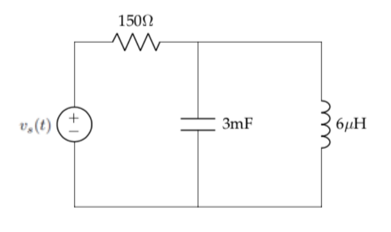
Find the equivalent impedance for the following circuit, given an input signal operating at 500Hz.

Understand: Here we have a circuit with series and parallel components and we need the equivalent impedance.
Identify Key Information:
Knowns: We know the individual values of resistance, capacitance, and impedance. Additionally, we know the specific operating frequency.
Unknowns: The individual impedances and the total equivalent impedance.
Assumptions: We are assuming the circuit is in sinusoidal steady state.
Plan: Since we want to combine the impedances, we can only do this if we first convert the individual component values to impedance. Then, we can use the series and parallel relationships we already know and love to consolidate the components.
Solve: First, we calculate the individual impedances:
Now, we have essentially replaced the inductor and capacitor with resistors. As such, we can combine the capacitor and inductor, which are in parallel:
Since \(Z_{eq1}\)is in series with the resistor, we can add the two together, leading to:
\(Z_{eq} = \ Z_{R} + Z_{eq1} = 150\Omega + j0.023\Omega\).
Answer: The equivalent impedance is \(150 + j0.023\Omega\).
Now that we’ve had some practice calculating impedances, we can combine the concept of impedance with Ohm’s law to find the unknown current of a circuit containing RLC components.
Example Problem 3#
Find the expression for the steady state sinusoidal current, is(t), that flows in the following circuit:

Understand: Here, we have a circuit with a sinusoidal input, a resistor, an inductor, and a capacitor. The end goal is to use Ohm’s Law (with complex numbers) to find the current.
Identify Key Information:
Knowns: We know the rectangular form of the input signal and the resistance, inductance, and capacitance of the components**.** Additionally, we know the frequency, so we can calculate the angular frequency, \(\omega\).
Unknowns: The polar and phasor form of the source.
Assumptions: We are looking for the sinusoidal steady state answer.
Plan: Although this problem seems daunting at first, if we can transform to the frequency domain, we can simply use equivalent impedances with Ohm’s Law in the same way we used equivalent resistances with Ohm’s Law in previous lessons. In order to transform to the frequency domain, we have to convert the input signal to phasor form, and then transform the components to impedances. From there, we can solve for the current using Ohm’s Law and find the rectangular form of the current, is(t).
Solve: First, we convert the input signal to phasor form (ensuring we use the RMS voltage for the magnitude). Recognizing that the frequency of the circuit will not change, we only need to track the amplitude and phase angle; the amplitude and phase can be used to write the output signal in the standard form at the end of the problem:
Next, we find the angular frequency.
\(\omega = 2\pi f = 2\pi(3.18\ Hz) = \ 20\) radians/s
We can use this angular frequency to find the impedances.
ZR = R = 40Ω
Now, since the components are in series and we have all the values in Ohms, we can simply add them together to get:
This leads to the following equivalent circuit:

Now, we can use Ohm’s Law to find the current:
We can use the magnitude (being sure to convert from RMS value to peak value) and the phase angle of the phasor to convert to rectangular (standard) form of the current. In doing so, we start with the AC equation for current, \(I_{m}\cos(360{^\circ}ft + \phi)\). Then, we set \(I_{m}\) equal to the RMS value of the phasor multiplied by \(\sqrt{2}\) and \(\phi\) equal to the phase angle of the phasor. Note that the frequency did not change from the source frequency.
Answer: The current is \(3.394\cos\left( 360{^\circ}(3.18\ Hz)t - {6.9}^{\circ} \right)A\)
Often, when doing analysis on RLC circuits, we want to find the voltage across a specific component – this will be what we refer to as our output voltage. In this case, we can use a voltage divider. To do this, we can use our voltage divider equation, but we replace the “R”s with “Z”s and use the phasor form of the voltage \(V_{total}\). Recall that voltage dividers only work with components placed in series, so the impedances must be in series when using a voltage divider.
Example Problem 4#
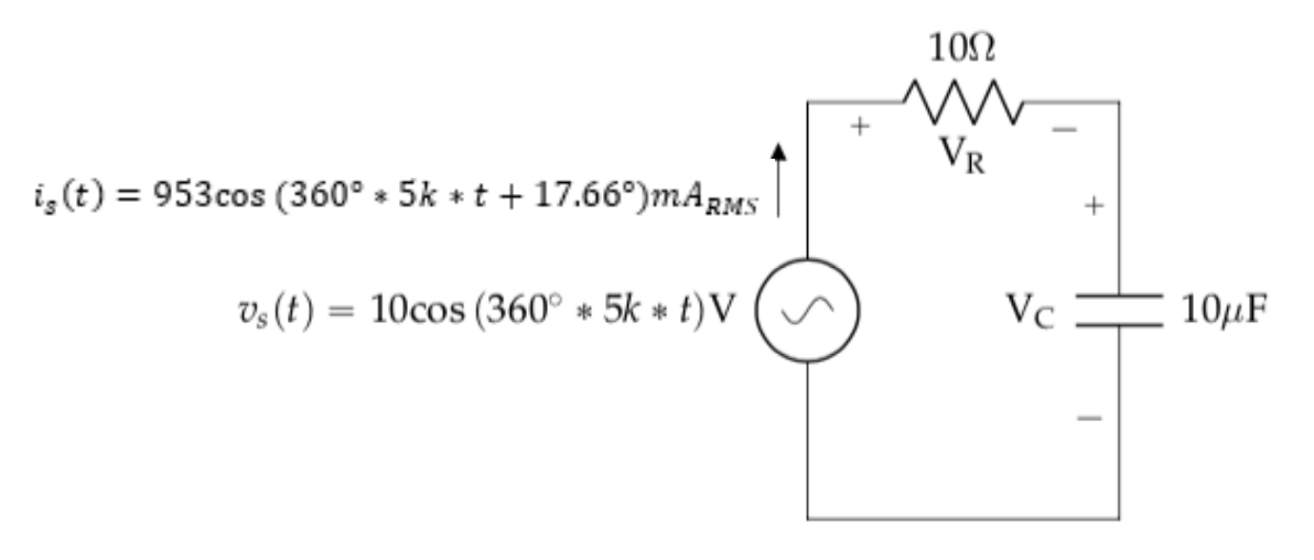
Find the ouptput voltage, VC.

Understand: Here, we have a circuit with a sinusoidal input, a resistor, and a capacitor. The output voltage is across the capacitor.
Identify Key Information:
Knowns: vs, Is, R, and C.
Unknowns: VR and VC, but we really are only looking for VC.
Assumptions: We are looking for the sinusoidal steady state answer.
Plan: We could use Ohm’s Law to calculate the voltage across the capacitor, or we could use a voltage divider. For the sake of practice and comparison, we will do both.
Solve: First, we will use Ohm’s Law to find the voltage VC. Since the current is given in the time domain, we need to convert IS to phasor form. Remember, the magnitude of the phasor term needs to be RMS, so we have:
Now we can solve for voltage \(V_{C}\)
Let’s confirm our result by using a voltage divider. First, we need to convert VS to phasor form. Remember, the magnitude of the phasor term needs to be RMS, so we have:
Now, since we already calculated the impedance of the capacitor, we know the equivalent impedance of the entire circuit, \(Z_{eq}\), is \((10 - j3.183)\Omega\), so we can find the voltage across the capacitor as:
Which is the same answer we got before. Notice that we started using our calculator to do the complex math – it certainly makes life easier if you take the time to configure your calculator to do that.
We can now convert our answer from phasor form into the rectangular form, being sure to convert the phasor magnitude from RMS back into an amplitude:
Answer: The voltage across the capacitor is \(3.03\cos(360{^\circ}*5k*t - 72.34{^\circ})V\).
