ICE 4: Stoplight#
Overview#
So far in this course you have implemented combinational logic on your FPGA. The ability to implement synchronous logic enables us to make finite state machines and greatly expands your ability to implement useful designs.
In order to accomplish this, we will expand our use of processes in VHDL.
Objectives#
Design the Stoplight FSM in VHDL
Test the Stoplight FSM in VHDL
Control a real world miniature stoplight.
End State#
Provide a demo to your instructor.
Ensure the following files are pushed to your repository:
VHDL files
Constraints (
.xdc).bitfile used to program board
Background#
You will design the stoplight to match the description given in the ICE 4 homework assignment.
Light turns green when car is present.
Light stays green while cars are present.
Cycles through yellow to red when a car is not present.
The system has three outputs (Red, Yellow, and Green) and must be implement with a Moore FSM as seen is Fig. 19.
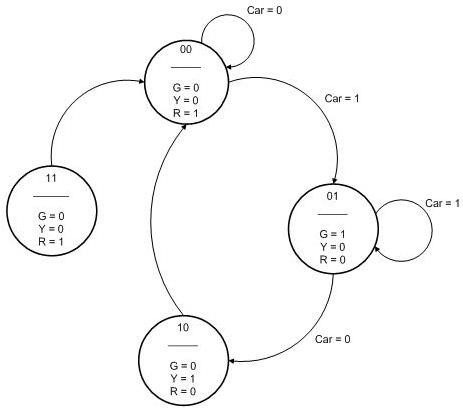
Fig. 19 Stoplight state transition diagram#
Setup Vivado#
Fork and clone ICE 4
Open the folder
Double click
stoplight.xprto open Vivado!
Tip
If you want, you can enable GitHub actions to run on your fork by going to your repository in the web browser and clicking the “Actions” tab. After you do this, subsequent commits will trigger and automated run of your stoplight_fsm testbench!
Modify headers and make an initial commit.
stoplight_fsm.vhd#
Entity#
The stoplight entity is given in stoplight_fsm.vhd as:
entity stoplight_fsm is
    port(
         i_C     : in  std_logic;
         i_reset : in  std_logic;
         i_clk   : in  std_logic;
         o_R     : out  std_logic;
         o_Y     : out  std_logic;
         o_G     : out  std_logic
        );
    end stoplight_fsm;
i_Cis the control signal to indicate if a car is presento_R,o_Y, ando_Gare outputs to control the colored lightsi_clkprovides a rising edge to drive the flip flopsi_resetwill reset the flip flops to their default state
STOP! Take out a physical or virtual piece of paper and draw your stoplight entity
Architecture#
Every finite state machine is going to have the same structure, as shown in Fig. 20
“Combinational” or “Next State” Logic
State Register (flip flops)
Output logic
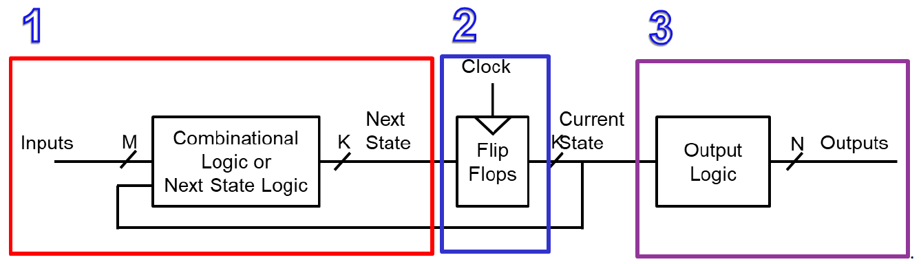
Fig. 20 Finite state machine structure#
You need to modify the architecture of your stoplight file to reflect the design shown in Fig. 21.
Note
This design looks more complicated than it actually is!
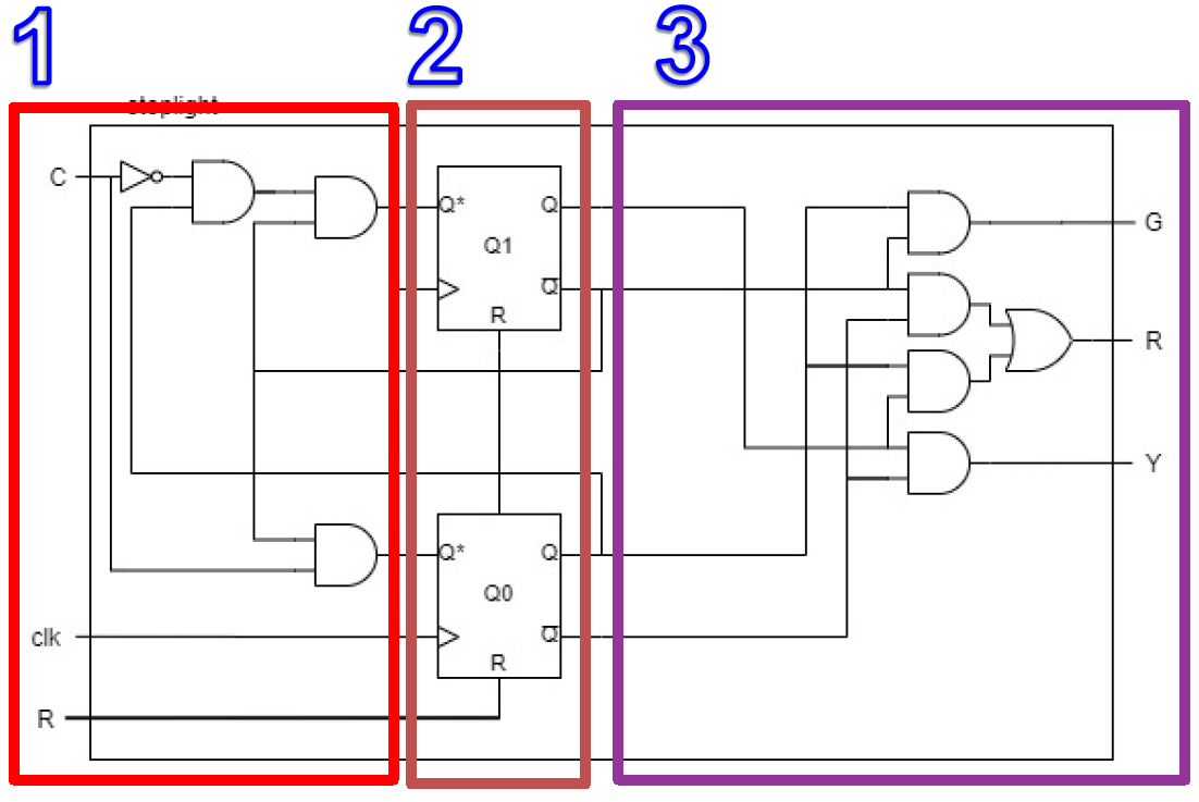
Fig. 21 Entity and architecture for implementing stoplight#
State Register#
First, we’ll implement Section 2: The State Register.
The state register for our stoplight is comprised of two flip flops. Each flip flop has a \(Q\) (current state) and a \(Q_{next}\) (next state). In order to represent three states, we need two bits, so both \(Q\) and \(Q_{next}\) must be represented with 2-bit vectors.
According to our VHDL naming conventions, we will prefix these signals with f_
to indicate the signal is used for sequential logic.
Warning
It is critical that you give f_Q and f_Q_next a default value.
Because the current and next states are dependent on each other,
an undefined value in either one could break your system
and leave it in an undefined state.
Even though the original problem didn’t specify, we are going to make
the yellow state our default (and our reset) state. To accomplish this,
the vectors need to be initialized with "10".
Hint
Default values can be set with the syntax :="10"; following
your initial signal declaration.
Create and initialize two 2-bit vectors:
f_Qandf_Q_next.
A “process” in VHDL#
Once the signals have been created, we can use them in our state register. The basis for a register in VHDL is a process. Declaring a process allows us to create a sub section of our hardware that is only triggered when certain signals change and is the only place we can implement sequential statements.
If you remember, we have actually been using processes with every ICE and lab… in our test bench!
Here is how to implement our register:
--- state memory w/ asynchronous reset ---
register_proc : process (i_clk, i_reset)
begin
    if i_reset = '1' then
        f_Q <= "10";        -- reset state is yellow
    elsif (rising_edge(i_clk)) then
        f_Q <= f_Q_next;    -- next state becomes current state
    end if;
end process register_proc;
---
Setup
The text preceding the key word “process” represents the name you are giving that process.
Unlike the test process, we have signals inside the parenthesis following the key word “process.”
These signals indicate which signals are going to trigger the process to run.
We have
i_resetbecause we want to implement an asynchronous reset.We have
i_clkbecause we want the process to run on a rising edge of the clock.
If reset
We check for the reset first because we do not wait for a clock edge… this is what makes it asynchornous.
If we waited for the clock then it would be a synchronous reset.
When we reset we want to go back to our yellow state of “10”.
Else If rising edge
The IEEE
std_logic_1164.vhdlibrary contains functions we can use.The
rising_edge()function “Detects the rising edge of a std_ulogic or std_logic signal. It will return true when the signal changes from a low value (‘0’ or ‘L’) to a high value (‘1’ or ‘H’).”It is only when we have a rising edge that a register (or flip flops)reads in a new value.
Once the rising edge is triggered we want to assign our current state
f_Qto becomef_Q_next.Because we made both
f_Qandf_Q_nextvectors, we don’t need to worry about individually assigning the bits; we can just setf_Q <= f_Q_next.If there is no rising edge then we simply exit the process.
Next State Logic#
Now that we have our register in place we can complete Section 1: Next State Logic.
We simply need to implement the Q_next(0) and Q_next(1) equations we developed in the ICE 4 homework assignment.
Implement these equations as combinational logic in your architecture.
Output Logic#
Our final step in creating our stoplight component is Section 3: Output Logic.
We simply take the equations from the ICE 4 homework assignment and implement them.
Implement these equations as combinational logic in your architecture.
Check syntax, then:
Commit your changes with git
stoplight_fsm_tb.vhd#
First, set stoplight_fsm_tb.vhd as top in simulation sources.
The testbench is already complete, so you do not need to add or change anything.
BUT! It and has two new aspects we’ll discuss.
The first is the declaration of a constant.
-- Clock period definitions
    constant k_clk_period : time := 10 ns;
As you can see from the name, we intend to use this constant to create an artificial clock to drive our FSM. When implementing our design on the board, we will use the clk we get from the board, but inside the test bench we must make a virtual clock.
Once the constant has been created, we can make a process to implement our clock:
-- Clock process
clk_proc : process
begin
    w_clk <= '0';
        wait for k_clk_period/2;
    w_clk <= '1';
        wait for k_clk_period/2;
end process;
Since a process runs in parallel with the rest of the circuit, this will run continually in the background. Essentially, this process sets the clock value low for exactly half of the period and then sets it high for half of the period creating an oscillating signal we can use as our clock.
Also, notice that we are still using assert statements, but now we wait for the
next rising edge before checking the for a value.
-- red light
w_C <= '0'; wait for k_clk_period;
    assert w_stoplight = "100" report "should be red when no car" severity failure;
Look through the
sim_procto see what the test bench is going to do.
Simulation#
Fig. 22 shows what your simulation should look like.
Understanding Waveform Signals & Default Behavior By default, the Vivado simulation waveform will only display the top-level signals that are explicitly declared in your test bench itself. Any signals internal to your instantiated subcomponents or lower-level modules are hidden to keep the workspace uncluttered.
However, viewing these internal signals is an incredibly useful tool when debugging your Finite State Machine (FSM) designs. By adding internal signals to your waveform, you can verify that both the current state and next state are behaving as expected, allowing you to isolate errors:
If the state transitions correctly but the output is wrong, the issue likely resides in your output logic equations.
If
f_Q_nextcalculates correctly butf_Qdoes not update, you may be resetting accidentally, or your clock process is incorrect.
How to Add Internal Signals To add a signal from any internal component to your waveform, follow these steps:
Click on “Window” in the top menu and select “Scope”.
In the Scope window, select the subcomponent to view its internal signals.
In the Objects window, highlight the specific signal you want to view (double-clicking the declaration will also highlight it).
Right-click on the highlighted signal and select “Add to Wave Window”.
Run the simulation again (re-launch or click run) to populate the new signals with data.
You will be prompted to save the waveform configuration. Click YES and add it to your project so you do not have to repeat this process.
Important
REQUIRED FOR SUBMISSION:
You must manually add the internal state signals
f_Qandf_Q_nextto your waveform before capturing your image. Submissions that do not show these signals in the waveform will be considered incomplete.You must run your simulation for 140ns. Simulations that are run for less than 140ns will not show the results for all functionality the test bench is verifying. Submissions ran for less than 140ns will be considered incomplete.
Ensure your waveform is legible. Missing/truncated signal names/values or compressed waveforms will result in lost points.
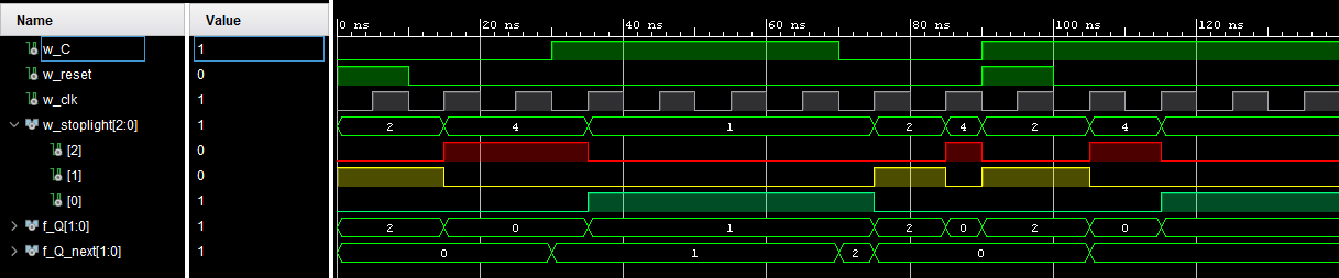
Fig. 22 Stoplight FSM Test Bench Waveform#
Take a screenshot of your waveform and commit it to your repo.
top_basys3.vhd#
Now that we have the stoplight FSM up and running, we need to create the top_basys3 design to connect it to the board’s hardware. We will do this with the provided top_basys3.vhd file as well is the schematic seen in Fig. 23.
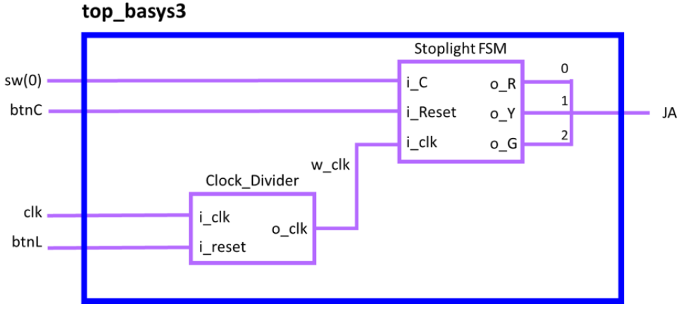
Fig. 23 top_basys3 design for stoplight ICE#
In order to fully implement this design, we have to introduce a new component that has been made for you.
The clock divider’s job is to take in the clock from the board, which operates at 100 MHz, and slow it down to a speed we can observe. For this ICE we will slow the clk down to 1 Hz.
component clock_divider is
    generic ( constant k_DIV : natural := 2 );
    port (  i_clk    : in std_logic;    -- basys3 clk
            i_reset  : in std_logic;    -- asynchronous
            o_clk    : out std_logic    -- divided (slow) clock
    );
end component clock_divider;
The module uses a generic natural constant called k_DIV to allow you
to dynamically set how much you want to slow the clock down. This is
done at instantiation using a generic map statement similar to port
mapping and has been done for you in the top_basys3.vhd file.
The i_reset on the clock will effectively pause the clock when a high signal
is received.
Explore the clock_divider to see if you can understand how it works.
A test bench has also been provided for the clock_divider. If you decide to run it, set the clock_divider_tb file as top and simulate.
Complete the file#
Much of the top_basys3.vhd file has been done for you, however, you need to declare the stoplight component and instantiated it. You also need to fill out the port map for the clk divider already declared and instantiated.
Complete top_basys3.vhd
Hardware test#
Connect stoplight#
Before we can test whether or not the stoplight works, we need to first connect the stoplight to the FPGA.
We will be using the Pmod connection on the side of the Basys3. Fig. 24 shows how to connect the wires to Pmod JA. Looking head on, the pins starting from the right and going to the left are red, yellow, green, empty, ground.
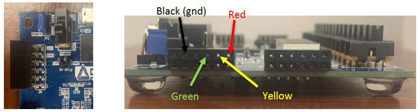
Fig. 24 Pmod from above and from the side with connection labels#
Luckily, the wires of the stoplight are color-coded! As you can see in Figure 10, black will go to black, red to red, yellow to yellow, and green to green.
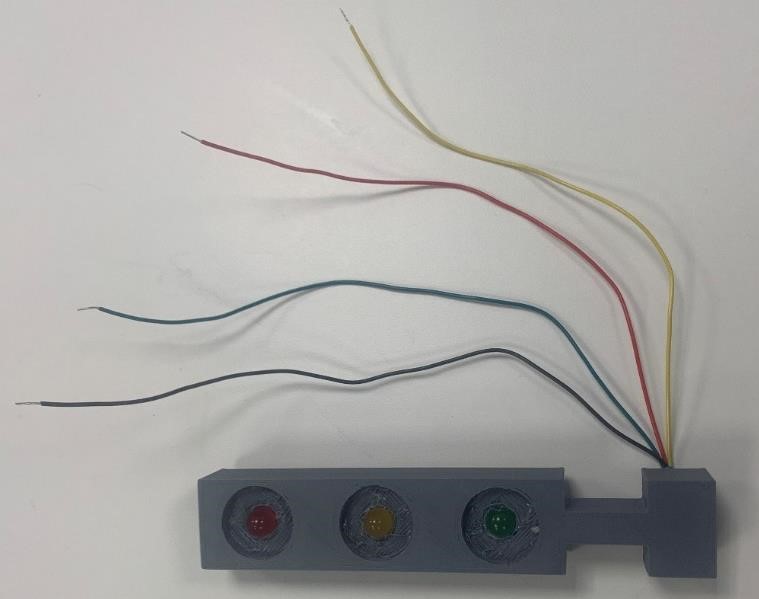
Fig. 25 Picture of stoplight model we will be using#
Test#
In order to use the clock we also need to employ the create_clock function. This specifies the period of the waveform in nanoseconds; in our case, for a 100MHz clock we need a 10ns period. In part, this helps define propagation delays for static analysis.
## Clock signal
set_property PACKAGE_PIN W5 [get_ports clk]
    set_property IOSTANDARD LVCMOS33 [get_ports clk]
    create_clock -add -name sys_clk_pin -period 10.00 -waveform {0 5} [get_ports clk]
The other pins are as normal.
Edit the constraints file to ensure that all signals from the top_Basys3 entity are uncommented.
Then:
Implement and generate bitstream. Push to your board.
Show an instructor that your design works! If you flip the car input on, the system should cycle from red to green. If you flip the car input off, the system should cycle to yellow, and then red. Pressing the center button should immediately turn on the yellow light and pressing the left button should pause the whole system.
Deliverables#
Double check that you have everything committed to your git repo.
Push the files.
Complete the (quick!) Gradescope assignment
Congratulations, you have completed In Class Exercise 4!