Lab 3 - Thunderbird Turn Signal#
Due: Lesson 17
Overview#
In this lab, you will design, write, test, and implement in hardware a finite state machine to simulate the taillights of a 1965 Ford Thunderbird.
This lab is modeled after a lab provided with instructor notes for Digital Design and Computer Architecture, David Money Harris & Sarah L. Harris, 2nd Edition.
Demo#
Here is a quick demo showing how your finite state machine for the taillights should function.
Collaboration#
All components of this lab are individual effort, although you can always discuss general concepts with other students.
Note
Do not show other students your working code. If helping another student, you can look at their code to help them troubleshoot it, but refer them to example code in the textbook, lecture slides, etc. to help them resolve the coding issue.
Background#

The 1965 Ford Thunderbird has three lights on each side that operate in sequence to indicate the direction of a turn. Video.
Fig. 36 shows the tail lights and Fig. 37 shows the flashing sequence for (a) left turns and (b) right turns.
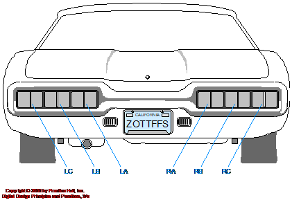
Fig. 36 Thunderbird taillights#
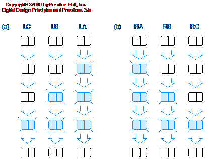
Fig. 37 Flashing sequence for taillights. The lights shaded light blue are illuminated.#
The objective of this lab is to create a turn signal that will engage the left and right light sets to mimic the Ford Thunderbird. This lab is divided into four parts: design (Prelab), VHDL creation, simulation, and implementation. If you follow the steps of FSM design carefully and ask questions at the beginning if a part is confusing, you will save yourself a great deal of time.
Prelab - FSM Design#
Project functionality description#
On RESET, the FSM should synchronously enter a state with all lights off.
When you press LEFT, you should see LA, then LA and LB, then LA, LB, and LC, then finally all lights off again.
This pattern should occur even if you release LEFT during the sequence.
If LEFT is still down when you return to the lights off state, the pattern should repeat.
The logic for the right lights is similar. RA is the LSB and RC is the MSB.
When both LEFT and RIGHT switches are on, your state machine should blink all lights on and off (implementing hazard lights).
Prelab Tasks#
You will use a Moore FSM to implement the above functionality.
Complete the following tasks to prepare yourself for the lab.
Create a state transition diagram using the
Lab3_StateTransitionDiagram_Template.pptxfound in Teams.Complete the binary encoding, state transition, and output tables using the
Lab3_Tables_Template.xlsxfound in Teams.Complete the one-hot encoding, state transition, and output tables using the second tab in the same template.
Select one of the two encodings and write the next state equations for your choice.
Write the output equations for the same choice.
Submit everything to Gradescope.
Submit everything to Gradescope.
In the remainder of the lab, you will be creating your FSM in VHDL, testing it using a testbench, and then implementing your design on the FPGA. Since you are designing a synchronous sequential circuit, we will be making use of a clock signal to drive the logic. Finally, while not required for the Prelab, you should already be thinking about what test cases you will use to verify that your design is correct.
Lab#
Fork and clone Lab 3
Open the project by double clicking
thunderbird.xpr.
Tip
Much of this code can be extracted from ICE4. Rather than open another Vivado project (and the confusion that comes with it), we suggest you view your ICE4 GitHub repository in your web browser.
thunderbird_fsm.vhd#
First, in the comments, add your state encodings.
Such as
-----------------------
--| One-Hot State Encoding key
--| --------------------
--| State | Encoding
--| --------------------
--| OFF   | 10000000
--| ON    |
--| R1    |
--| R2    |
--| R3    |
--| L1    |
--| L2    |
--| L3    |
--| --------------------
Or
--| Binary State Encoding key
--| --------------------
--| State | Encoding
--| --------------------
--| OFF   | 000
--| ON    |
--| R1    |
--| R2    |
--| R3    |
--| L1    |
--| L2    |
--| L3    |
--| --------------------
Next, declare the following entity:
entity thunderbird_fsm is
    port (
        i_clk, i_reset  : in    std_logic;
        i_left, i_right : in    std_logic;
        o_lights_L      : out   std_logic_vector(2 downto 0);
        o_lights_R      : out   std_logic_vector(2 downto 0)
    );
end thunderbird_fsm;
Note that we expect the inside right taillight, RA, to be the LSB of o_lights_R,
and RC should be the MSB.
Complete the architecture for
thunderbird_fsm.vhdby adding the necessary signals, next state logic, output logic, and state register.
thunderbird_fsm_tb.vhd#
Next, write a testbench that verifies functionality of your FSM. Make sure you carefully consider what test cases you need to run. For instance, what happens if you change an input in the middle of a blinking pattern? In your test bench comments, explain at a high level the various tests you conduct in plain English.
We recommend that you start off with a basic set of test cases first.
Make sure the first test you run is to apply a reset. This should put your FSM in a known good state.
Do not forget that you must create a clock process to drive the FSM.
Define a constant for a clock period of 10ns and use the constant throughout your testbench file.
Assert statements#
We expect you to follow the examples in ICE4’s stoplight_fsm_tb.vhd
to write some assert statements. However, as we move into larger
and more complex projects, you will no longer be able to write exhaustive tests.
Instead, shoot to hit:
The core functionality
Anything that seems tricky and likely to mess up
Cases where failure is catastrophic.
Even then, you may not be able to hit them all, and that’s ok! You should also leverage your waveform for testing.
Waveform#
For the simulation waveform in your testbench, you should include at a minimum the following signals in order:
i_clki_reseti_lefti_righto_lights_Lo_lights_RCurrent state bits
Next state bits
You do not need to change any signal colors, but expand your lights output busses so that the progression of lights can be easily seen.
Have an instructor verify your waveform. Add a screenshot of the waveform to your repository.
Markdown syntax for including an image in README.md

top_basys3.vhd#
Once you have verified that your FSM works correctly in simulation, create a top-level module and implement the hardware interface in Fig. 38 similar to the one pictured below.
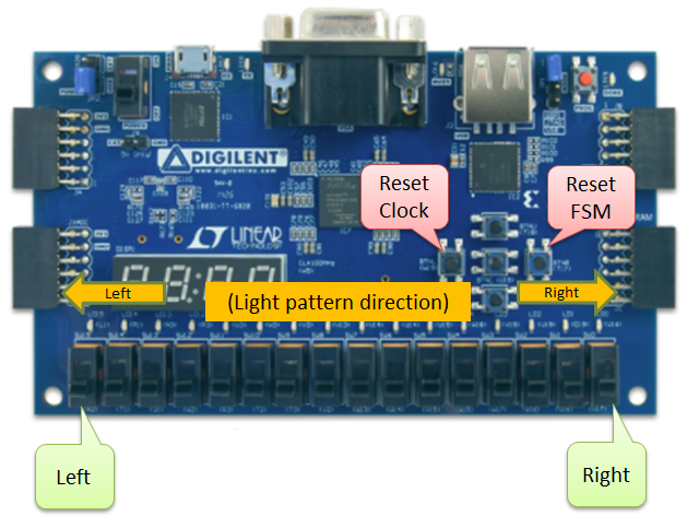
Fig. 38 Your super-sweet thunderbird control panel.#
You will need to ground any unused LEDs, but you can leave unused switches unconnected. In both cases, Vivado will generate warnings, but they may be safely ignored. The hardware interface pictured above is simply an example, so feel free to modify your design as desired.
Hint
Because of VHDL’s type system, you cannot “swap” bit order in a vector
by simply replacing downto with to.
Instead, you’ll have to find a different solution to make sure your right
turn signal does indeed progress to the right!
Basys3 Clock#
Note, the Basys3 board provides a built-in 100-MHz clock. This is a bit
too fast for our application, so you are also provided a VHDL module
(clock_divider.vhd) that will take in the fast 100 MHz clock, and
produce a slower clock that will make your thunderbird_fsm transitions
visible to the human eye. This is the same clock_divider you used in
ICE4,
though we are using it to obtain a different clock speed.
Your top-level design must incorporate a structural connection of the
thunderbird_fsm and clock_divider to produce a correct design.
Tip
You need to declare a temporary signal to “wire” the connection between the clock divider’s output clock port and the FSM’s input clock port.
You are not using the clock_divider as in input to the top_basys3; you are only using it to slow down the thunderbird_fsm operation enough to allow human observation of the inputs.
If you are a fighter pilot, you may omit the clock and rely on your superhuman reaction times.
To help you understand how the clock_divider module works, a test bench
has been provided. Note how the clock is instantiated. The module uses a
generic natural constant called k_DIV to allow you to dynamically set
how much you want to slow the clock down. This is done at instantiation
using a generic map statement similar to port mapping.
For top_basys3.vhd you can copy much of the clock_divider_tb.vhd code, but
you need to determine the correct k_DIV amount to slow the clock from 100MHz down to 4Hz.
Reading the VHDL comments and viewing the simulation waveform should help you
understand the appropriate value you need.
Before you write the architecture, neatly create a diagram (Excalidraw, draw.io, PowerPoint, ect. – do not hand draw it) showing your top-level entity and its internal architecture.
Complete your top level diagram.
Implement in Hardware#
In order to use the clock we also need to employ the create_clock function. This specifies the period of the waveform in nanoseconds; in our case, for a 100MHz clock we need a 10ns period. In part, this helps define propagation delays for static analysis.
## Clock signal
set_property PACKAGE_PIN W5 [get_ports clk]
    set_property IOSTANDARD LVCMOS33 [get_ports clk]
    create_clock -add -name sys_clk_pin -period 10.00 -waveform {0 5} [get_ports clk]
Uncomment the other necessary lines in your constraints file.
Then
Demo your working design to your instructor. This must happen after showing your waveform.
Deliverables#
Hardware Demo#
Show your instructor your waveform before demoing the hardware.
Using left and right switches generates correct LED patterns with changes occurring at a rate of 4 Hz
Holding the clock reset freezes the light patterns
Pressing the FSM reset resets the light patterns
Demo can be performed live with an instructor OR via a video link
You must show good test cases for full credit!
Code#
Submit your code via Gradescope. The autograder should pass!
Written Report#
You are not required write an entire lab report. Only complete the following sections:
Title Section
Abstract
Methodology (Design Description section only)
In the Design Description section, be sure to include:
functional description of the system
block diagram(s) showing major components and signal flow (hint: a state transition diagram would work well here)
description of inputs, outputs, and internal signals
NOTE: When you include an image, figure, block diagram, equation, etc., you need to discuss them in the text of your report.