Lab 4 - Moore Elevator Controller#
Overview#
This lab is all about designing complex systems!
To do this you will need to pull together building blocks from several previous labs and ICEs!
The prelab is on Gradescope; it will require you to make a copy and clone usafa-ece/ece281-lab4
Important
Only need to edit top_basys3.vhd.
All other VHDL files and your constraints file are ready-to-go; do not edit them.
This is to emphasize modularity (and competing internal requirements 😉)
Single-Elevator Controller#
The first iteration of this lab is implementing the Basic Elevator Controller (ICE5) on the Basys3 board with the user interface seen in Fig. 39
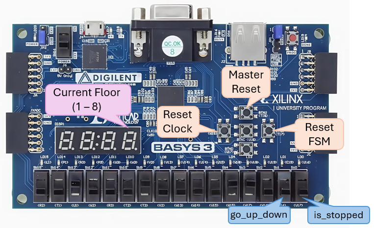
Fig. 39 Single-Elevator Controller User Interface#
The elevator’s current floor is shown on seven-segment display 0 (rightmost… doesn’t match picture above)
Disable unused displays
The elevator takes 0.5 seconds to move between floors
The display updates according to the output
The elevator must not teleport… no skipping floors
Three push buttons are to be used for resets
The Master Reset button resets both the FSM and the clock.
The reset floor is floor 2.
LED 15 must be tied to the clock signal that drives the FSM.
You may use the other LEDs for debugging. For example, outputting the current floor in binary. Otherwise they should be grounded.
Tip
You should checkout how the template implements the elevator FSM. It uses a fancy VHDL thing that is handy when scaling to a large number of sequential states!
Demo this to a classmate prior to starting on Multi-Elevator Controller.
Git commit and push.
Multi-Elevator Controller#
Expand the basic functionality above. Before you start editing the VHDL you must update your prelab diagram!!! We highly recommend that you check this diagram with an instructor (or at least a classmate).
Danger
If you don’t update your diagram first, you are probably going to waste Alot of time.

Add a second elevator FSM
Connect this second elevator to use
sw(15)for Up/Down andsw(14)for Stop.Connect it to the same reset signal as the first FSM.
Display the floor on display 2 (second from left).
Set unused displays (3 and 1) to
F(for “floor”)
Simulation#
Simulation is not required for this Lab, and you can jump directly to hardware implementation.
Note
A brief discussion on testing philosophy.
The type of testing you choose results in a tradeoff of complexity vs. how much confidence your test gives you that your design works.
Each component within your top_level already has been simulated and tested. This is known as unit testing because you make sure that each unit (component) does what it is supposed to. Unit tests give you confidence that a single thing works and they are quick to write and run. But unit tests don’t give you any information on how components will or won’t work together.
Integration testing tests if multiple units work together; for example, does the clock_divider indeed provide a slow clock to the FSM? Often this is the sweet spot of complexity vs. confidence, but not always.
Finally, end-to-end testing tests if everything works together. Unfortunately, end-to-end tests are also very complex to design and maintain.
As engineers, part of our job is to determine what is the appropriate level of confidence and justify designing tests to meet that level.
Deliverables#
Demo multi-elevator functionality by uploading a video to Teams > ECE281 > General > Files > Demos > Lab 4 > section. Name your video
lastname1_lastname2_demo.mp4Git commit and push
Submit code to Gradescope
Write lab report (template in Teams)