ICE 5: Basic Elevator Controller#
Overview#
In this in-class exercise, you design an elevator controller that will traverse four floors (numbered 1 to 4). You will only simulate your design; you will not implement it in hardware during this ICE.
Objectives#
Create and simulate a synchronous sequential logic system
Use VHDL to build a provided state diagram.
Write a testbench for a synchronous system to fully simulate the state machine’s operation.
System Specification#
Your elevator controller will traverse four floors (numbered 1 to 4).
Two external inputs,
i_up_downandi_stop.When
i_up_downis ‘1’ andi_stopis ‘0’, the elevator will move up until it reaches the top floor (one floor per clock, of course).When
i_up_downis ‘0’ andi_stopis ‘0’, the elevator will move down until it reaches the bottom floor (one floor per clock).When
i_stopis ‘1’, the system always stops at the current floor.When the elevator is at the top floor, it will stay there until
i_up_downgoes to ‘0’.When the elevator is at the bottom floor, it will stay there until
i_up_downgoes to ‘1’.The system should output the floor it is on (1 - 4) as a four-bit binary number,
o_floor.i_resetsynchronously puts the FSM into state Floor 2.
This description is translated into a state diagram shown in Fig. 26.
Inputs:
    i_up_down : '1' is Up, '0' is Down
    i_stop    : '1' is Stop, '0' is Go

Outputs:
    o_floor:
        Floor 1: "0001"
        Floor 2: "0010"
        Floor 3: "0011"
        Floor 4: "0100"
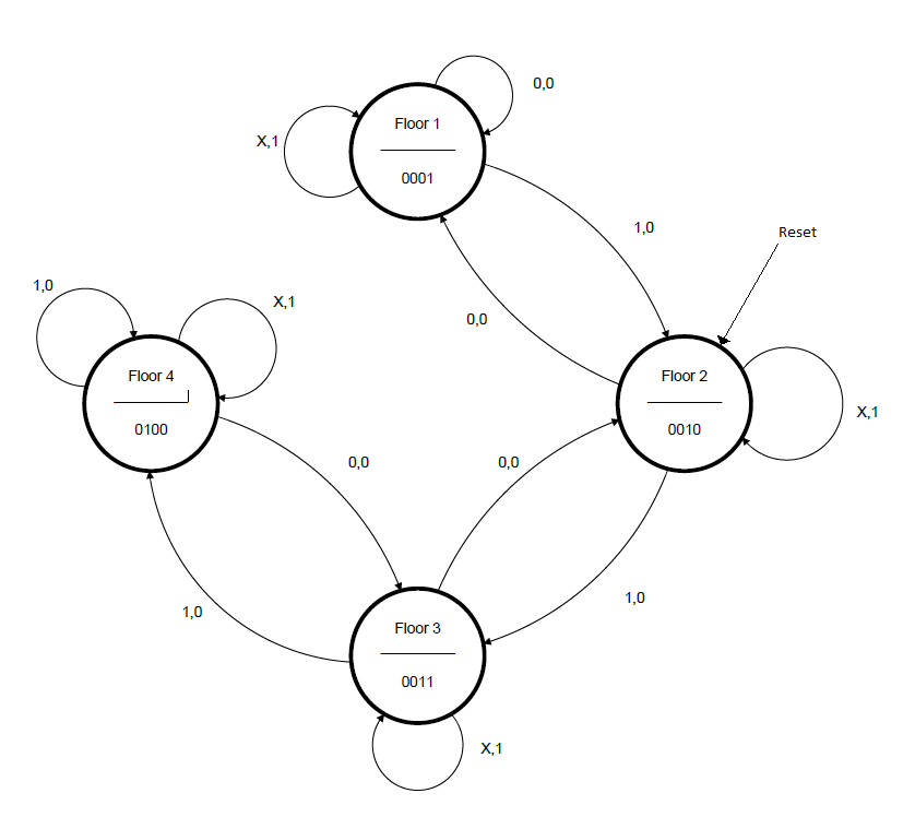
Fig. 26 Elevator controller state machine#
Setup Vivado#
Fork and clone ICE 5
Open the folder
Double click
elevatorController.xprto open Vivado!
Modify headers and make an initial commit.
elevator_controller_fsm.vhd#
The entity description has been completed for you.
State register process#
Recall that i_reset should be synchronous! Reference Lesson 22 Note Taker.
The reset state is Floor 2.
Because i_stop effectively functions as an enable, we can handle it
in our state register implementation.
Effectively, (if reset is low) then current state gets next state only when the rising clock edge and the elevator is not stopped. Otherwise, we stay at our current state (floor).
This allows us to greatly simplify our next state and output logic! See below.
Enumerated types#
This template has already been loaded with enumerated types for your states.
Enumerated types allow you to define your next state and output logic in terms of the state name instead of bits! This means you don’t have to create the equations for a chosen encoding type. Vivado gets to take care of that for you.
type sm_floor is (s_floor1, s_floor2, s_floor3, s_floor4);
Here we have the type sm_floor which can be any one of the four provided states.
We can also make signals of this type! This signal can be assigned the values
defined above.
signal f_Q, f_Q_next : sm_floor;
You can use an enumerated type for conditional assignments!
See VHDL Reference.pdf on Teams.
Because we handled i_stop in the state register (see above),
our concurrent logic here can be greatly simplified.
We provide a shell. The < > symbol represents a placeholder.
The ... means you need additional lines of logic.
-- Next State Logic
f_Q_next <= <state> when (<condition>) else -- going up
            ...
            ...
            ... -- going down
            ...
            ... else
            ...; -- default case
-- Output logic
with f_Q select
    o_floor <= <value> when s_floor1,
            ...
            ...
            <value> when others; -- default is floor1
The entity declaration has been completed for you.
Use a synchronous reset for your controller FSM
Hint
We recommend that you handle i_stop logic in your process.
This will save you lots of lines in the concurrent statements.
Also, think about how nested if statements and elsif are helpful.
Read through the provided code and comments, and then build the state machine in VHDL.
elevator_controller_fsm_tb.vhd#
We provide a component declarations, port maps, and simulated clock.
All you need to do is complete the test_process.
Make sure you hit:
Reset
Elevator going up
Elevator going down
Elevator waiting on floors
Elevator stopping on top floor (while going up)
Elevator stopping on bottom floor (while going down)
Add the
f_Qandf_Q_nextsignals to your waveform.Save the
.wcfgAdd a screenshot to your repository
Deliverables#
Git commit and push
Upload a screenshot of your waveform to Gradescope.