ICE 6: Time Division Multiplexor#
Overview#
In this in-class exercise, you will learn how to use the Time Division Multiplexor (TDM) by building a test bench for it and simulating. This will be directly applicable to creating your elevator controller in Lab4.
A TDM allows you to rapidly switch between multiple data sets. This is especially useful when you only have one channel on which to send data (your seven segment display for instance). The TDM operation is fairly simple. It is driven by a clock and cycles between N different inputs (in this case 4) continuously. Only one of the 4 inputs comes out of the TDM at a time.
Objectives#
Understand Time Division Multiplexing
Prepare for Lab 4
End State#
This ICE requires a Gradescope submission with short answer questions, but there is no demo requirement!
Additionally, there is a GitHub Action testbench that should pass. Ensure your two VHDL files are pushed to your repository.
Setup Vivado#
Fork and clone ICE6
Open the folder.
Double click
tdm.xprto open Vivado!
Modify headers and make an initial commit
Time Division Multiplexing#
Time Division Multiplexing (TDM) is a method of transmitting multiple signals over a single communication channel. It works by dividing the available time on the channel into smaller time slots, with each slot allocated to a different signal. By rapidly switching between these time slots, TDM allows multiple signals to be transmitted simultaneously without interfering with each other.
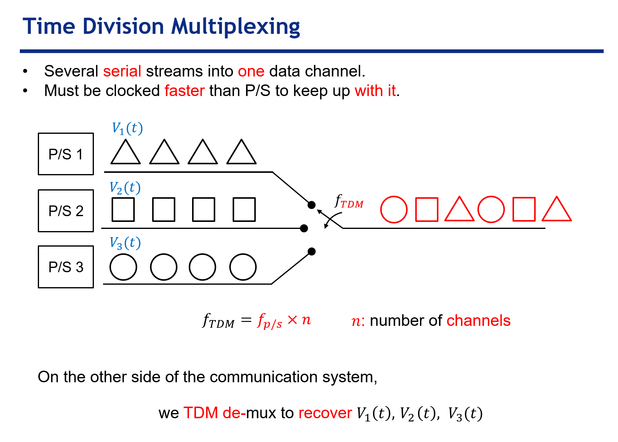
Fig. 27 TDM with shapes on \(n = 3\) channels by switching at frequency \(f_{TDM}\)#
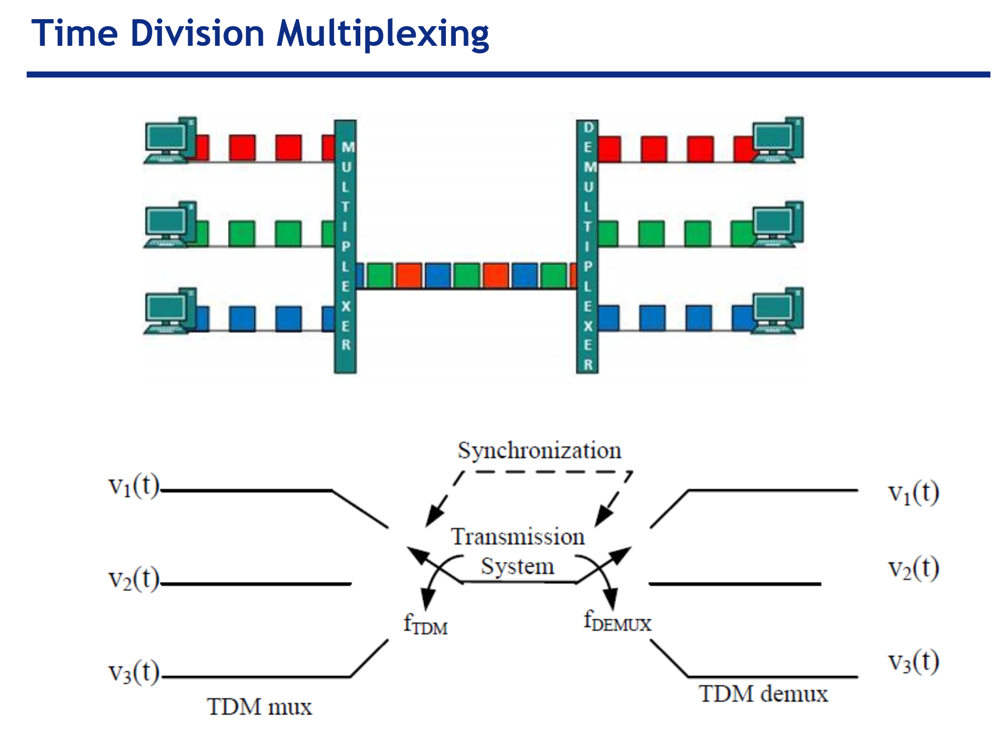
Fig. 28 Demuxing after transmission to get data back in to separate channels.#
TDM4.vhd#
The file is already completed for you! But please read this section.
Again, a TDM outputs a single one of its inputs at a time based on time. This is like a normal MUX, but instead of using a select signal to determine which input becomes the output, a TDM uses time to determine which input becomes the output.
Entity#
Lets start by going through each of the signals in a TDM entity with four data sets.
entity TDM4 is
    generic ( constant k_width : natural  := 4); -- bits in input and output
    Port ( i_clk    : in  STD_LOGIC;
        i_reset  : in  STD_LOGIC; -- asynchronous
        i_D3     : in  STD_LOGIC_VECTOR (k_WIDTH - 1 downto 0);
        i_D2     : in  STD_LOGIC_VECTOR (k_WIDTH - 1 downto 0);
        i_D1     : in  STD_LOGIC_VECTOR (k_WIDTH - 1 downto 0);
        i_D0     : in  STD_LOGIC_VECTOR (k_WIDTH - 1 downto 0);
        o_data   : out STD_LOGIC_VECTOR (k_WIDTH - 1 downto 0);
        o_sel_n    : out STD_LOGIC_VECTOR (3 downto 0) -- selected data line (one-cold)
    );
end TDM4;
k_widthis a generic constant. A constant is a set value used elsewhere (like our test bench clock period). The generic terminology means it is a value that can be set by the user when they instantiate the component. We will discuss later how it impacts this designi_clkis an input signal which drives the TDM. You will connect it to your test bench’s simulated clki_resetis an input signal which resets the TDM which sets the output toi_D0.i_D3is the first of 4 data sets which are passed into the TDM. Notice that it is a vector of(k_width -1 downto 0). This means ifk_widthis 4 theni_D3is a 4-bit vector from 3 downto 0.k_widththen allows the user to determine how big of a vector is going to be passed through. We will use 4 in this example, but if you were to use this with your seven segment decoder you could set it to 7.i_D2is the second of 4 data sets which are passed into the TDM.i_D1is the third of 4 data sets which are passed into the TDM.i_D0is the fourth of 4 data sets which are passed into the TDM.o_datarepresents the output of the TDM. At any point in time it will be one ofi_D3,i_D2,i_D1, ori_D0.o_sel_nis an output vector that tells the user which of the input channels has been selected. It is one cold meaning “0111” indicatesi_D3, “1011” indicatesi_D2, “1101” indicatesi_D1, and “1110” indicatesi_D0. You will not need to use this signal in this exercise, other than to verify it is indeed working.
Important
k_width determines how wide the data vectors are.
Each of the i_Dx signals are what is being multiplexed.
In this case, we have four input signals (i_D0-3),
each of which is k_width := 4 bits wide.
To add more inputs to MUX you need to add more
i_Dxstd_logic_vectors.To change how many bits each input transmits, you need to change
k_widthand the size of the declared std_logic_vectors.
Architecture#
We introduce a new type in the signal declaration: unsigned. The unsigned type can take basic arithmetic operations, such as addition!
 -- 2 bit counter output to select MUX input
signal f_sel_n : unsigned(1 downto 0) := "00";
Read the
twoBitCounter_procand understand the lifecycle off_sel_n.Read the two MUXs in concurrent statements and understand what’s going on.
TDM4_tb.vhd#
Use the provided
TDM4_tb.vhdfile.Finish the component declaration started in the test bench.
Declare the required constants
k_clk_periodis type time set to20 nsk_IO_widthis type natural set to4
Declare the required signals
w_clk,w_resetw_D3,w_D2,w_D1,w_D0, andf_dataf_sel_n
Complete the port map
Finish setting up the clk process to drive the TDM. This should resemble the FSM test benches.
The only thing we have left is to define our input vectors. Generally, when using the TDM these inputs will come from somewhere else (the output of your basic elevator controller in Lab 4, for instance).
However, in this test we are going to hard code inputs. Assign the following values to the data inputs under the comment
---assign the values to data inputs
w_D3 <= ...
...
i_D3gets “1000”i_D2gets “0100”i_D1gets “0010”i_D0gets “0001”
Finally, set your simulation to run for only 160 ns and run it. You should get a waveform that looks like Fig. 29.
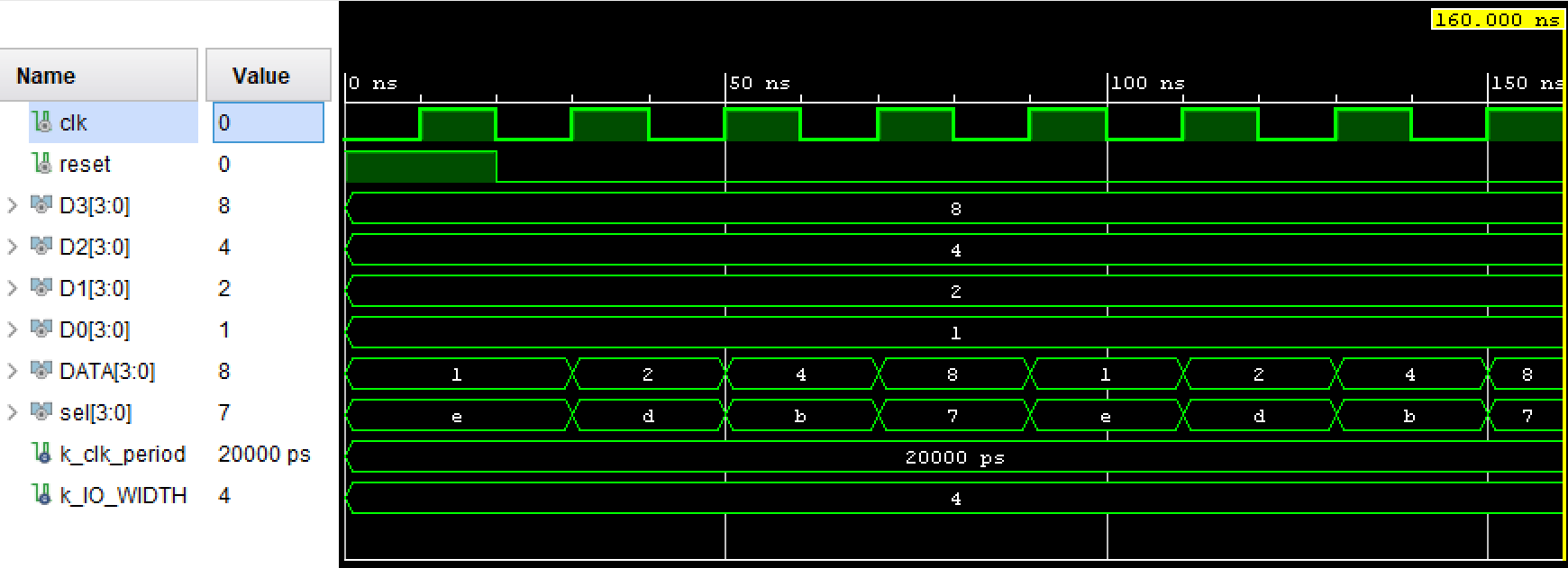
Fig. 29 Simulation waveform#
Deliverables#
The Gradescope submission includes several short answer questions.
Deliverable |
Points |
|---|---|
Gradescope Submission |
50 |
Passing GitHub Action |
50 |