HW 7 - ICE3: Full Adder#
The intent of this HW is to start thinking about reusing components to make more complex things.
Half adder, once more#
In HW 6 you previously created a half adder in Digital.
Full adder#
To make a full adder we are going to connect two half adders!
First, read the ICE3 Background section to learn what a full adder is and how to make it with two half adders.
After reading the background section:
Open Digital, then click File > New embedded Circuit
Instead of making a half adder all over again, go Components > Custom > halfAdder !
Do that again to get your second half adder.
Add an OR gate
Add inputs and outputs and give them the following exact labels:
CinABCoutS
Connect everything like this - but the pants are your halfAdder component, which appears as a box.
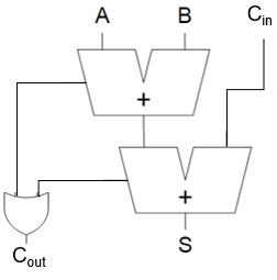
Start simulation and test! It should match the full adder truth table.
Tip
In Digital go to Analysis > Analysis (or press F9) to open up a truth table!
Save your final schematic as fullAdder.dig
Later, when we build this in VHDL we will connect switches and LEDs to the inputs and outputs, respectively.
Submission#
Zip both halfAdder.dig and fullAdder.dig and upload to the gradescope assignment.
Important
You must use the exact label names that we specified above, otherwise the autograder will not work.
This is actually very realistic; engineers have to design interfaces that work with external systems according to published standards!