🔬 Lab 11 Serial Ports#
📌 Objectives#
Students should be able to develop device drivers for the Universal Asynchronous Receiver/Transmitter (UART) and Synchronous Peripheral Interface (SPI).
Students should be able to measure UART and SPI signals using a logic analyzer and analyze the binary bits.
Note
The best thing about a Boolean is even if you are wrong, you are only off by a bit.
📜 Synopsis#
In this lab, our aim is to develop software modules capable of communicating with external devices connected by the most commonly-available serial communication interfaces. Specifically, we will establish communication between the MSP432 and the Nokia 5110 using a Serial Peripheral Interface (SPI), and we will connect our PC’s USB port to the MSP432 using a Universal Asynchronous Receiver-Transmitter (UART).
💻 Procedure#
Write UART functions in UART0.c#
Write
UART0_Init()Follow the steps in the code and Appendix 1 from Lecture 11.
Write
UART0_OutChar()Wait for TXBUF to be empty (UCxTXIFG)
Send data using TXBUF
Hint: Read
UART0_InChar()and Lecture 11.
Write
UART0_OutString()A NULL-terminated string is a string with the NULL character at the end of it.
The NULL character is 0 (ASCII: 0), not ‘0’ (ASCII: 0x30). You can find the ASCII table on ECE 382 Ref Guide, Valvano pp. 60, or here.
Transmit one character in the string at a time until you reach the end of the string. Do not transmit the NULL character. Do not rewrite the code you already wrote.
Note
The NULL character should not be confused with a null pointer, which is a pointer or reference that points to an invalid object or to nothing. For instance, consider the declaration
int* x;where the pointer x initially doesn’t point to any valid address until you assign one to it.Debug (or F11)
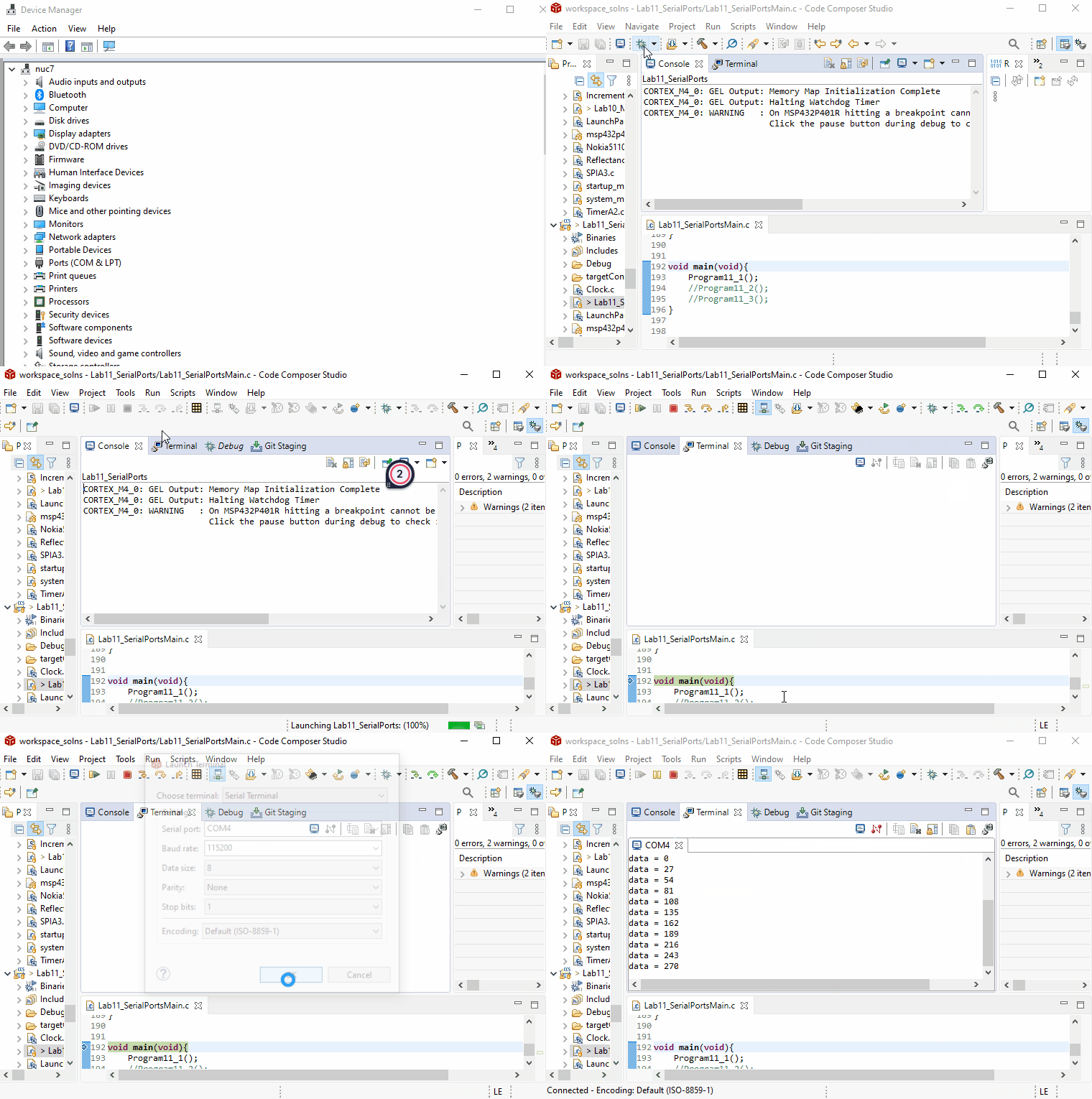
Program11_1but do not clickResume(or F8) yet.Open Windows Device Manager and go to Ports.
Find the COM port for
XDS110 Class Application/User UARTGo to CCS and open the
Terminaltab under theViewmenu.Open a new terminal and select the COM port you found in Device Manager.
Click
Resume(or F8) to continueProgram11_1.It will print strings and numbers in the serial terminal as shown below.

Take a screenshot of the serial terminal displaying the header strings and a few lines of data in the while-loop. You can pause your program and use the Snip & Sketch tool to take a screenshot.
Submit the screenshot on Gradescope.
Q&A
Q: Did anyone else have the problem where the terminal was showing only high numbers under the “Serial Terminal” option (COM9-COM12)? My app keeps crashing when I try to run the terminal on one of these. I’m getting the right values otherwise and my code works fine.
A: It can be. It depends on how many serial devices have been connected to your computer. I once had something like COM24.
Test UART0 with Moku:Go#
Replace Baek in
char Name[] = "Baek"beforeProgram11_2with the first three letters of your last name. Use your first name if your last name is less than three letters long.Warning
Turn off the robot before connecting the logic analyzer to it. Otherwise, you might short-circuit and damage the board!
Connect Moku:Go Logic Analyzer to your LaunchPad.
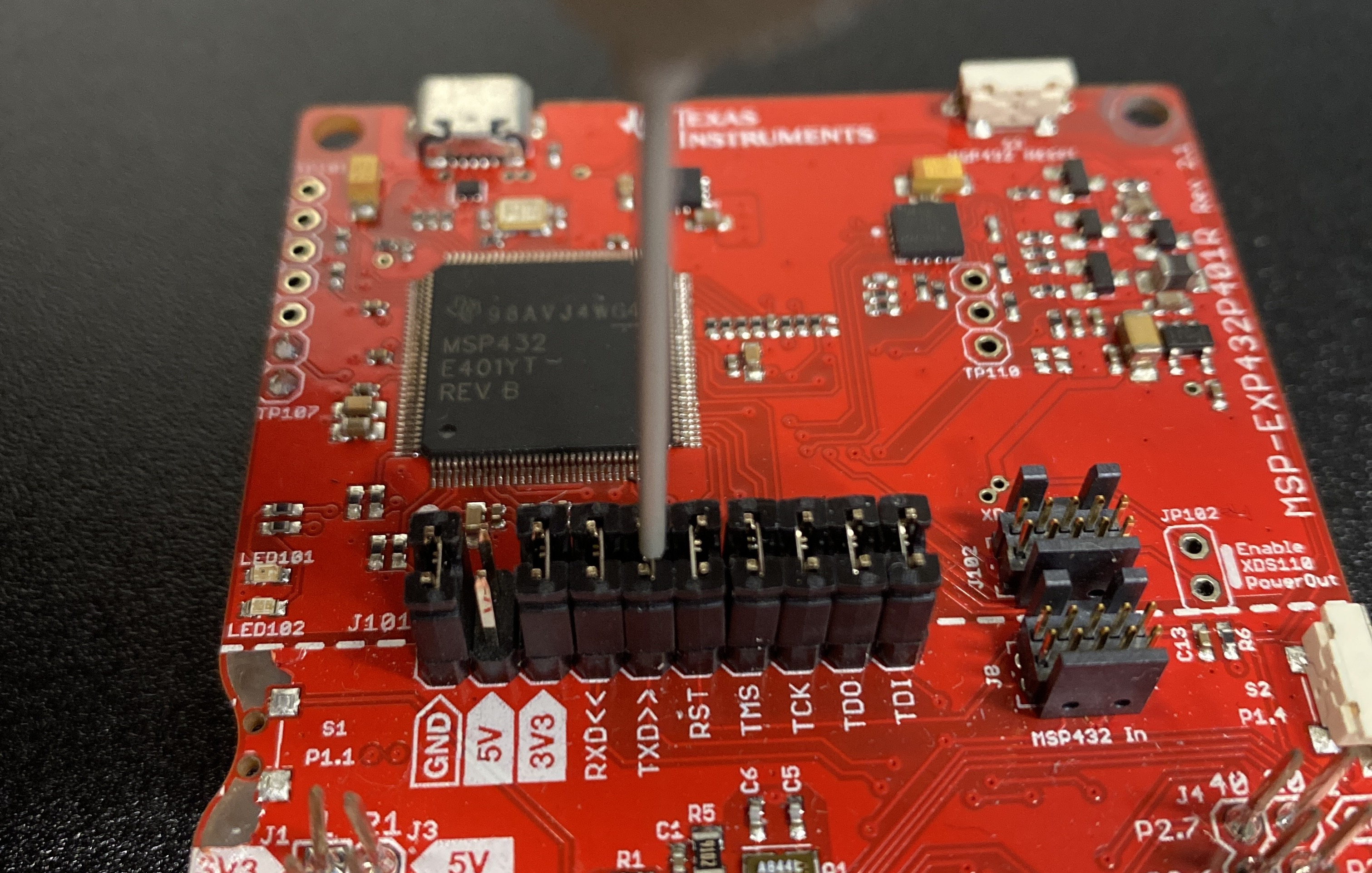
Connect the 20-pin I/O port to Moku:Go.
Connect Pin 1 of the Logic Analyzer to the TXD port on your LaunchPad.
Connect a Logic Analyzer’s ground pin (black wire) to one of the LaunchPad ground pins.

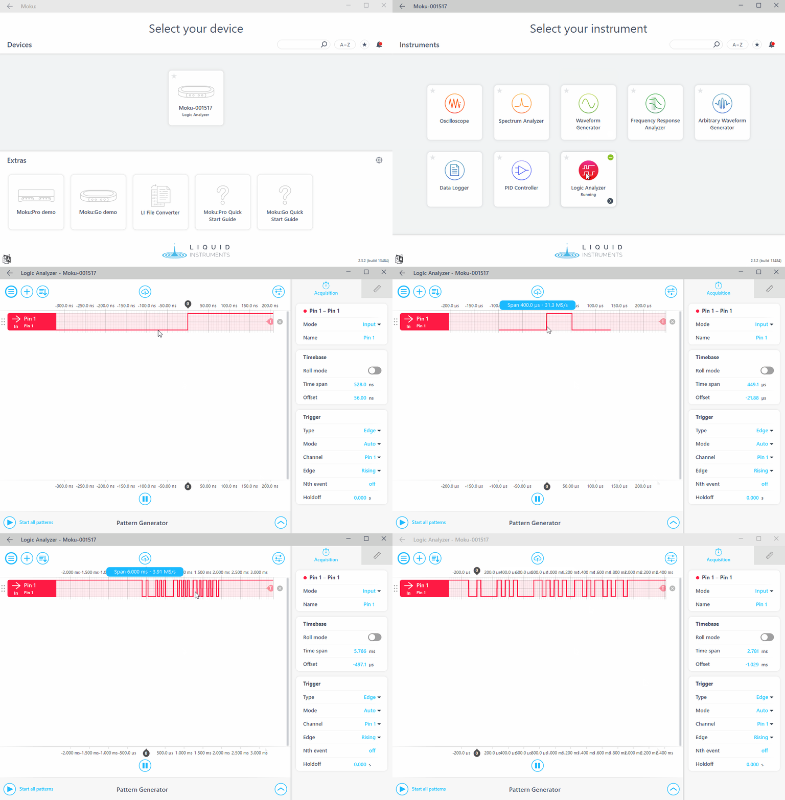
Run
Program11_2and start Moku:Go Logic Analyzer to measure the signal transmitted from the UART2 port of your LaunchPad as shown below.Scroll your mouse wheel up or down to display the entire signal. If you don’t have a scroll wheel, change the
Time spanvalue under theAcquisitiontab.
Take a screenshot and clearly annotate start bits (S), stop bits (E), and the binary bits of your three letters as shown below.
Add your three letters under the corresponding binary signals.
You can find an ASCII binary table here.

Write SPI functions in SPI_A3 and Test with Moku:Go#
Implement
SPIA3_Init(),SPIA3_Wait4Tx(),SPIA3_WriteTxBuffer(),SPIA3_OutChar(), andSPIA3_OutString(). For guidance on how to use these functions, refer toNokia5110_Init(),Nokia5110_OutChar(), anddatawrite()in theNokia5110.cfile. Hint:SPIA3_OutChar()should integrate the operations ofSPIA3_Wait4Tx()andSPIA3_WriteTxBuffer(). Do not call these functions directly within theSPIA3_OutChar(); Instead, incorporate their logic directly into the function.Run
Program11_3and start Moku:Go Logic Analyzer to measure the signal transmitted from the SPI_A3 port of your LaunchPad.Warning
Turn off the robot before connecting the logic analyzer to it. Otherwise, you might short-circuit and damage the board!
Connect Moku:Go Logic Analyzer to your LaunchPad.
Connect three Logic Analyzer probes to P9.4 (STE), P9.5 (CLK), and P9.7 (MOSI) of your LaunchPad.
Connect a Logic Analyzer’s ground pin (black wire) to one of the LaunchPad ground pins.
Take a screenshot of the signal below and clearly annotate the binary bits of your three letters.
Add your three letters under the corresponding binary signals.

Note
Program11_3bypasses the Nokia5110 module and directly accesses the SPIA3 serial port, which means the LCD cannot be used for this section.
🚚 Deliverables#
Deliverable 1#
[6 Points] Run
Program11_1()to transmit strings via USB/UART and take a screenshot of the serial terminal displaying the strings. Submit a screenshot of your Serial Terminal on Gradescope.
Deliverable 2#
[6 Points] Run
Program11_2()to transmit your name via UART. Submit a screenshot of Moku:Go Logic Analyzer. Annotate three letters of your name and their binary values.
Deliverable 3#
[6 Points] Run
Program11_3()to transmit your name via SPI. Submit a screenshot of Moku:Go Logic Analyzer. Annotate three letters of your name and their binary values.
Deliverable 4#
[6.5 Points] Push your code to your repository using git. Ensure you comment on your code.
This lab was originally adapted from the TI-RSLK MAX Solderless Maze Edition Curriculum and has since been significantly modified.
