🔧 Assembly#
Assembly Questions#
Why do I need to preserve R2 before calling my function if it only uses R0 and R1?#
According to AAPCS, a subroutine can freely modify R0-R3 & R12. You claim that “my” function only uses R0 and R1. Firstly, when developing software or hardware, there is rarely individual ownership as it belong to the team. All the code developed belongs to the team, not any specific individual. I have never seen an engineer/programmer working alone like Tony Stark. Engineers/programmers work in a team of ~10 – 1000, and anyone in the team can modify your code. So, you MUST comply with standards. Second, you may want to claim that my approach is more efficient. However, efficiency is not the primary concern. Just like stopping at a stop sign is mandatory, regardless of whether a car is coming or not, many other standards, such as safety standards, must be followed. Therefore, always bear in mind that R0-R3 and R12 can hold different values after calling subroutines.
Why does ADD not update Program Status Register (PSR)?#
The textbook (pp. 64) says, “The N, Z, V, C, and Q bits give information about the result of a previous ALU operation.”
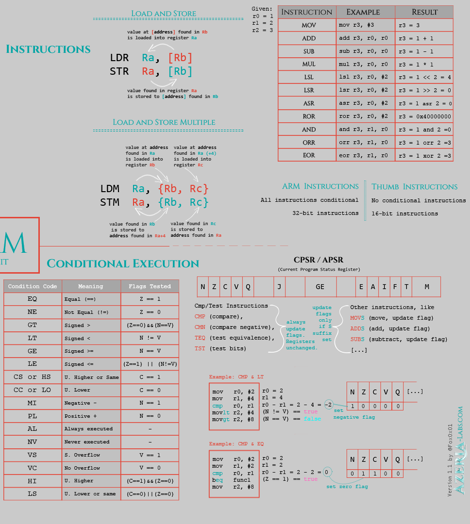
Although ADD and SUB are ALU operations, they do not update the PSR register. If you want to update them, you must use ADDS and SUBS instead. CMP always updates the PSR flags.
With SUBS you can replace
    SUB R0, #1   ; R0 = R0 - 1
    CMP R0, #0   ; R0 == 0 ?
    BEQ  Label1  ; go to Label1 if R0 == 0
with
    SUBS R0, #1   ; R0 = R0 - 1
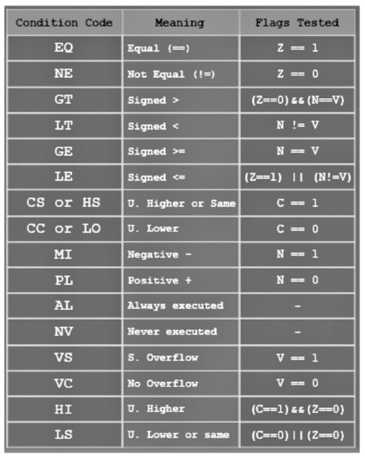
    BEQ  Label1   ; go to Label1 if R0 == 0, EQ tests Z == 1
Can R0 and R1 be saved in the Stack (Push/Pop)? I thought it was only R4-R11 that would be able to be stored in a stack.#
Yes, they can be stored in the stack, whereas R4-R11 must be because you have to restore them if you change them in your function. You can store R0-R3, R12 in the stack to preserve them before calling a function in case the function contaminates them. However, you don’t want to do that because it takes time. Memory access is generally ~100-1000 times slower than register access. So, you had better store R0-R3 to R4-R11 instead.
You may insist you would not want to push R4-R11 if you are using them for R0-R3, which still causes memory to be used. You are right, but if you have used R4-R11 for something else, you have already pushed them. Otherwise, there is no reason to push R0-R3 because a function can freely modify R0-R3.
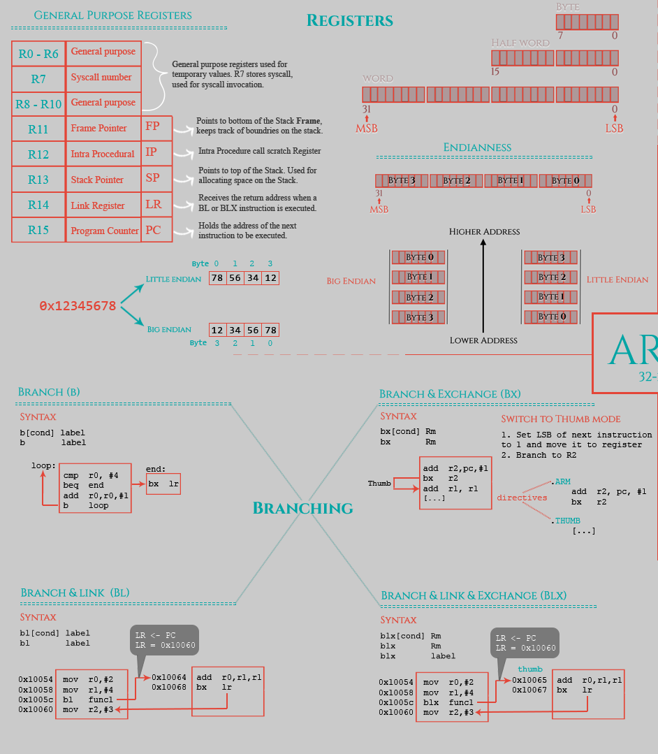
ARM Cortex-m Assembly cheat sheet#


ARM Cortex-m Assembly Conditional Flags#

ARM Instruction Reference#
ADD and SUB: 32-bit addition and subtraction#
Examples:
    ADD R3, R2, R1     ; R3 = R2 + R1
    ADD R3, R2         ; R3 = R3 + R2 (R3 += R2)
    ADD R3, R2, #100   ; R3 = R2 + 100 (#100 is a 12-bit immediate value between 0 - 4095)
    ADD R3, #1         ; R3 = R3 + 1 (R3++)
    SUB R3, R2, R1     ; R3 = R2 - R1
    SUB R3, R2         ; R3 = R3 - R2 (R3 -= R2)
    SUB R3, R2, #100   ; R3 = R2 - 100 (#100 is a 12-bit immediate value between 0 - 4095)
    SUB R3, #1         ; R3 = R3 - 1 (R3--)
MUL and UDIV#
Multiply (MUL) and unsigned divide (UDIV)
Examples:
    MUL  R3, R2, R1     ; R3 = R2*R1
    MUL  R3, R2, #2     ; ERROR
    UDIV R3, R2, R1     ; R3 = R2/R1
    UDIV R3, R2, #2     ; ERROR
AND, ORR, EOR, and BIC: 32-bit bitwise AND, OR, Exclusive OR, and Bit Clear#
Examples:
    AND R3, R2, R1      ; R3 = R2 & R1
    AND R3, R2, #0xFF00 ; R3 = R2 & 0x0000FF00
    ORR R3, R2, R1      ; R3 = R2 | R1
    EOR R3, R2, R1      ; R3 = R2 ^ R1  (exclusive or)
    BIC R3, R2, #0xFF00 ; R3 = R2 & 0xFFFF00FF
    BIC R3, R2, R1      ; R3 = R2 & ~R1
MOV: 32-bit Move#
The MOV instruction copies values into registers. This instruction is useful for moving values from one register to another, and initializing registers to a constant value.
Note: you cannot use MOV to move data from/to memory. You must use LDR or STR
Examples:
    MOV R3, R2         ; R3 = R2
    MOV R3, #0xFA05    ; R3 = 0x0000FA05
    MOV R3, #10        ; R3 = 10
Incorrect Uses:
    MOV R3, [R2]          ; Can't move from the address in R2.  Must use LDR instead.
    MOV R3, #0xFF00FF00   ; 0xFF00FF00 is a 32-bit.  The range is 0-65535 (2^16-1)
LDR: Load from memory into a register#
The LDR instructions copy values from memory into registers.
Examples:
    LDR  R3, [R2]      ; Load 32-bit from address in R2 to R8
    LDRB R3, [R2]      ; Load 8-bit from address in R2 to R8
    LDR  R3, [R2, R1]  ; Load 32-bit from address in R2 + R1 to R8
    LDR  R3, [R2, #5]  ; Load 32-bit from address in R2 + 5 to R8
    LDR  R3, [R2], #5  ; Load 32-bit from address in R2 to R8, then R2 = R2 + 5
    LDR  R3, [R2, #5]! ; R2 = R2 + 5, then load 32-bit from address in R2 to R8
    LDR  R3, Pi        ; R3 = 314159

Pi  .word 314159       ; Pi is the address of the constant 314159.
Incorrect Uses:
    LDR R3, R2        ; R2 must be [R2] if the value of R2 is an address. Otherwise, it must use MOV R3, R2
    LDR R3, #0xFF00   ; 0xFF00 is not an address
STR: Store from register into memory#
The STR instructions copy values from registers to memory.
Examples:
    STR  R3, [R2]      ; Store 32-bit value of R3 into address R2
    STRB R3, [R2]      ; Store 8-bit value of R3 into address R2
    STR  R3, [R2, R1]  ; Store 32-bit value of R3 into address R2 + R1
    STR  R3, [R2, #5]  ; Store 32-bit value of R3 into address R2 + 5
    STR  R3, [R2], #5  ; Store 32-bit value of R3 into address R2, then R2 = R2 + 5
    STR  R3, [R2, #5]! ; R2 = R2 + 5, then store 32-bit value of R3 into address R2
ASR, LSL, and LSR: arithmetic shift right, logical shift left, and logical shift right#
ASR, LSL, and LSR move the bits in the register to the left or right by the number of places specified by constant.
Note that arithmetic left shift is identical to logical left shift.
Examples:
    ASR  R3, R2, #3    ; R3 = R2 >> 3, signed, similar to R3 = R2/8
    ASR  R3, R2, R1    ; R3 = R2 >> R1, signed, similar to R3 = R2/(2^R1)
    LSL  R3, R2, #3    ; R3 = R2 << 3, similar to R3 = R2*8
    LSL  R3, R2, R1    ; R3 = R2 << R1, similar to R3 = R2*(2^R1)
    LSR  R3, R2, #3    ; R3 = R2 >> 3, similar to R3 = R2/8
    LSR  R3, R2, R1    ; R3 = R2 >> R1, similar to R3 = R2/(2^R1)
CMP: 32-bit compare#
The CMP instruction compares two values. This instruction updates the N, Z, C, and V flags according to the difference between the two values.
Examples:
    CMP  R3, #6400 ; Compare R2 with #6400. Updates the N, Z, C, and V flags according to R3 - 6400
    CMP  R2, R3    ; Compare R2 with R3. Updates the N, Z, C, and V flags according to R2 - R3
B: Branch instructions#
The B instructions cause a branch to label.
Examples:
    B    label    ; branch to label
    BEQ  label    ; conditional branch to label if equal ==
    BNE  label    ; conditional branch to label if not equal !=
    BLE  label    ; conditional branch to label if less than or equal, signed <=
    BLT  label    ; conditional branch to label if less than, signed <
    BGE  label    ; conditional branch to label if greater than or equal, signed >=
    BGT  label    ; conditional branch to label if greater than, signed >
    BLS  label    ; conditional branch to label if lower or same, unsigned <=
    BLO  label    ; conditional branch to label if lower, unsigned <
    BHS  label    ; conditional branch to label if higher or same, unsigned >=
    BHI  label    ; conditional branch to label if higher, unsigned >
BL: Branch link (call subroutine)#
BL is the call to subroutine (function) instruction. The address of the subroutine is specified by the label. The BL instruction also saves the return address (the address of the next instruction) in the Link Register (LR).
Examples:
BL Func ; Call to Func, save the return address in LR.
If you use B Func, it will call Func, but it will not return to the next instruction because the B instruction does not save the return address in LR.
BX: Branch indirect#
BX is a branch indirect instruction, with the branch address indicated in Rm.
Examples:
    BX  LR    ; jump to the place specified by LR. return at the end of function call
    BX  R0    ; jump to the place specified by R0. We don't use this in ECE382.
PUSH and POP#
PUSH stores registers on the stack in order of decreasing register numbers, with the lowest-numbered register using the lowest memory address and the highest-numbered register using the highest memory address.
POP loads registers from the stack in order of increasing register numbers, with the lowest-numbered register using the lowest memory address and the highest-numbered register using the highest memory address.
Curly brackets are needed on the registers for push and pop i.e. PUSH {LR}. Here is how to push and pop multiple registers.
    PUSH {R4-R6}
    PUSH {R9}
    PUSH {LR}

    POP {LR}
    POP {R9}
    POP {R4-R6}
The push and pop operations use a memory stack, accessed in an orderly manner called last-in-first-out (LIFO). So, the last thing you push must be popped first. However, the order does not matter when you push and pop multiple registers.
    PUSH {R4, R5, R6, R9, LR}
    POP {R4, R5, R9, R6, LR}  ;  order does not matter
The order does not have to be the same for ARM 32-bit processors because they always go into the same relative positions, regardless of the order of appearance inside the curly brackets ({ }). The lowest-numbered register is stored and loaded first when you push and pop multiple registers in a single pop/push instruction.
Here is a even more elegant way to push and pop multiple registers.
    ; even better way
    PUSH {R4-R6, R9, LR}
    POP {LR, R4-R6, R9, LR}       ;  order does not matter
ARM Directives#
.text: Places following objects in flash ROM.data: Places following objects in data memory (RAM).space: Reserves space in bytes, uninitialized in RAM.string: Allocates one or more bytes of memory from a string literal.word: Places 32-bit words into memory.byte: Places bytes into memory.align 2: skips 0 to 1 byte to make next halfword aligned.align 4: skips 0 to 3 byte to make next word aligned.global: import/export function between files.asmfunc: signifies the start of an assembly function.endasmfunc: signifies the end of an assembly function.end: end of file
