🔬 Lab 13 Timers#
📌 Objectives#
Students should be able to write software module that generates periodic interrupts to run user-specific tasks.
Students should be able to generate PWM signals using a timer module.
Students should be able to use PWM outputs to adjust the motor speeds.
Note
Make it work, make it right, make it fast. – Kent Beck
📜 Synopsis#
Lab Overview: Motor Power Control#
This lab aims to write software that independently adjusts the power delivered to two DC motors. You will generate Pulse Width Modulation (PWM) outputs on pins P2.6 and P2.7, which connect to the Enable (EN) pins of two TI DRV8838 motor drivers.
PWM Period: Fixed at 20 ms (50 Hz).
Motor Response: At 50 Hz, the motors will not respond to individual high/low digital pulses. Instead, they respond to the average voltage level. The delivered power (\(P\)) is defined by:
Where \(V\) is voltage, \(I\) is current, and \(d\) is the duty cycle percentage (\(d \in [0.0, 100.0]\)).
Representing the Duty Cycle: Fixed-Point Scaling#
In embedded systems, representing the duty cycle as a standard percentage (like \(45.5\%\)) poses a challenge:
The Problem: Microcontrollers often lack floating-point units (FPUs). Additionally, doing math with floating-point numbers (e.g., float duty = 45.5) is computationally expensive and slow.
The Fixed-Point Solution: To keep our calculations fast and efficient, we must use integers. However, if we restricted ourselves to integer percentages (\(0%\) to \(100%\)), we would only have 101 discrete speed settings.
The Scaling Hack: To get decimal-level precision using only integers, we multiply our percentage values by 10. This shifts the decimal point out of the way.
Instead of writing 45.5% (which requires a float), we write 455 (an integer).
Instead of a maximum value of 100%, our maximum integer value becomes 1000.
This “parts per thousand” representation is formally known as permille.
If using a standard 16-bit integer (from 0 to 1,000) to represent the duty cycle:
An integer value of 0 represents a 0.0% duty cycle.
An integer value of 500 represents a 50.0% duty cycle.
An integer value of 1000 represents a 100.0% duty cycle.
Note
For this lab, your code should cap the maximum safe output at 99.9% to prevent constant “on” states, so your integer range will span from 0 to 999.
💻 Procedure#
Setup#
Before proceeding, review the solution for TimerA1_Init posted on Gradescope to confirm you have the accurate code. If the solution isn’t available on Gradescope, consult your instructor to go over your code.
Write Timer functions in TimerA1.c.#
Open
TimerA1.handTimerA1.cand read them thoroughly.Carefully examine
Program13_1to understand (i) howTimerA1is initialized and (ii) how the semaphore is employed to coordinate between the foreground and background threads.Write the
TimerA1_Stop()andTA1_0_IRQHandler()functions, as discussed in Lecture 13 and referenced in Valvano’s textbook.Demonstrate
Program13_1as shown in the video below. Ensure that the red LED blinks at 5 Hz, the blue LED blinks at 2.5 Hz, and the LCD updates the elapsed time at a rate of 5 Hz. Your demo should also show the timer interrupt being enabled by pressing a switch and disabled by pressing a bump sensor.
Video Credit: C24 Chanon Mallanoo
Important
Why do we employ a function pointer?
We want to enable interrupt service routines to execute a range of user-defined tasks without the need for rewriting them each time a new task arises. As an illustration, when we have different tasks for TimerA1 to execute, we don’t have to rewrite the TimerA1.c file. Instead, we can create functions that carry out these tasks and simply pass their addresses to TimerA1.
Write functions in PWM.c and Motor.c.#
Thoroughly review the documentation provided in
PWM.handPWM.cto understand the functions you will implement.Note that the PWM period for both motors is set at 20 ms (50 Hz). When calling
PWM_Init34fromMotor.c, you should use a period value of 15,000, corresponding to the PWM period of 20 ms. It is not the Timer period, as explained in Lecture 13 Slide 17.Keep in mind that the duty cycles passed into
PWM_DutyRightandPWM_DutyLeftare in permille. The code handles the conversion to the Timer period, so you don’t need to perform this calculation when calling these functions in Motor.c.Read
Motor.handMotor.cthoroughly.Implement the functions in
PWM.cto generate two PWM outputs controlling the robot’s wheels. Both PWM signals operate at 50 Hz (20 ms).Demo
Program13_2as shown in the video below. Use motor functions defined inMotor.cto maneuver the robot and ensure you run at least two iterations in the while loop.
Video Credit: C26 Peter Choi, Royal Military College of Canada
Write functions in Lab13_Timersmain.c#
Write
Program13_3().Combine the
PWMandTimer_A1periodic interrupt functionality into one software system that controls the robot likeProgram 13_2, but uses the periodic interrupt to track the time elapsed.While the Timer interrupt runs in the background, the foreground thread will display the motor functions on the LCD.
As shown in the component block diagram below,
PWM.cis not directly accessible toProgram13_3; It is encapsulated inMotor.c.Program13_3will only use the functions in Motor.c to control the motors.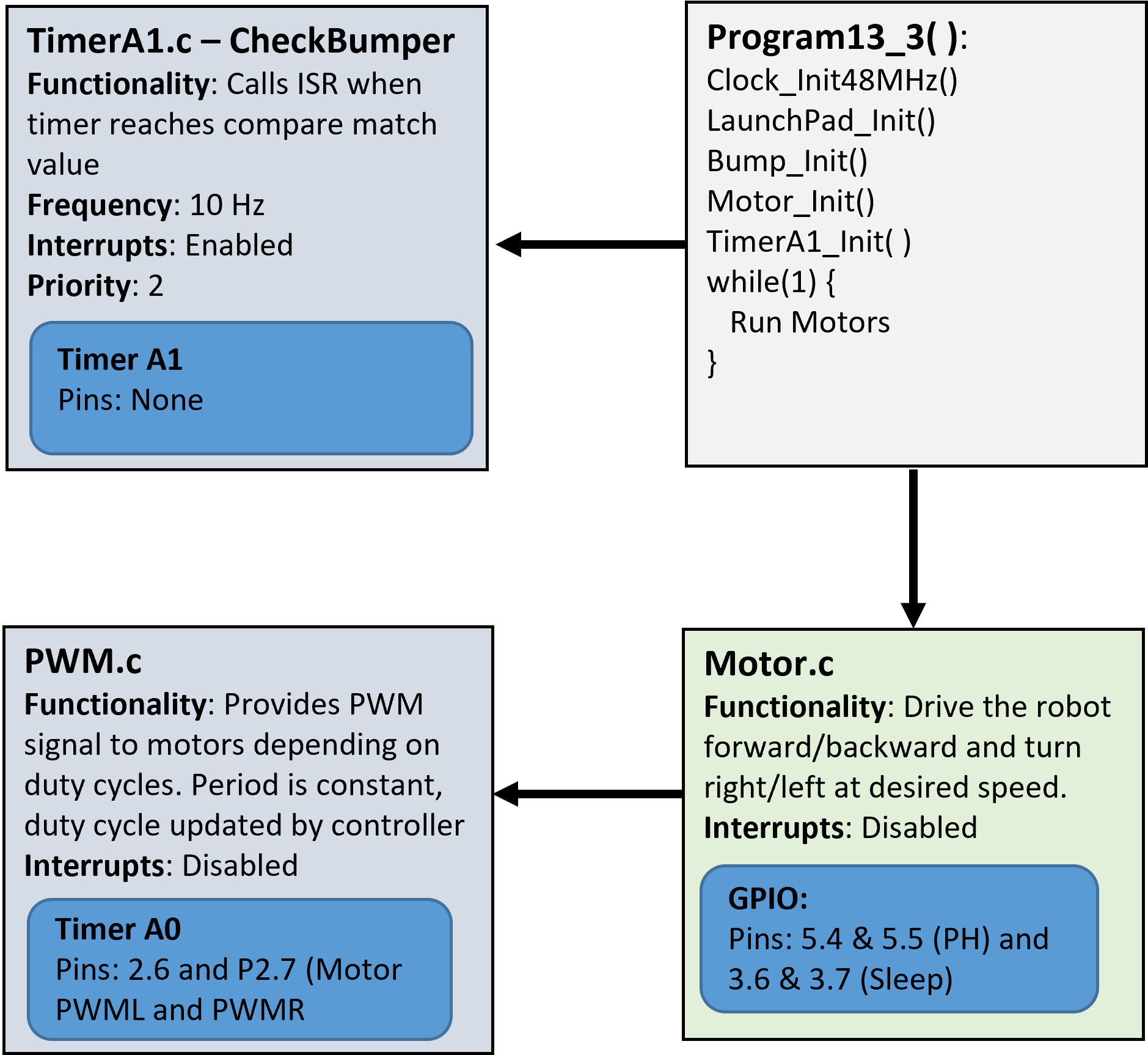
Demo
Program13_3as shown in the video below.
Video Credit: C26 Peter Choi, Royal Military College of Canada
🚚 Deliverables#
Deliverable 1#
[6 Points] Demo
Program13_1(). UseTimerA1to blink the red LED at 5 Hz while the blue LED blinks at 2.5 Hz and the LCD updates the elapsed time at 5 Hz. Your demo should also show the timer interrupt being enabled by pressing a switch and disabled by pressing a bump sensor. During the demo, explain what you are demonstrating.
Deliverable 2#
[7 Points] Demo
Program13_2(). Use motor functions defined inMotor.cto move the robot. You must run at least two iterations in the while loop. During the demo, explain what you are demonstrating.
Deliverable 3#
[7 Points] Demo
Program13_3(). Use PWM to move the robot like Program13_2, but use TimerA1 to periodically track the time elapsed. You must run at least two iterations in the while loop. During the demo, explain what you are demonstrating.
Deliverable 4#
[9.5 Points] Push your code to your repository using git. Write comments in your code.
This lab was originally adapted from the TI-RSLK MAX Solderless Maze Edition Curriculum and has since been significantly modified.