🔬 Lab 14 Real-Time Systems#
📌 Objectives#
Students should be able to implement software for edge-triggered interrupts to detect collisions.
Students should be able to utilize shared global variables as a means of communication between threads.
Students should be able to utilize interrupt priority to establish the execution order when handling multiple concurrent events.
Note
Any fool can write code that a computer can understand. Good programmers write code that humans can understand.
📜 Synopsis#
The aim of this lab is to utilize edge-triggered interrupts for detecting collisions through the bump sensors while the robot is in motion. When a collision event occurs, it should trigger an interrupt, and the reading of the bumper switches should be handled within the interrupt service routine (ISR).
In previous labs, we assigned high priority to periodic interrupts to ensure real-time execution of user tasks. For instance, in Lab 13, we updated PWM duty cycles in real time. However, in Lab 14, the collision task requires an even higher priority than the periodic tasks because collisions represent potentially dangerous conditions that demand immediate attention. In this lab, you’ll transition from periodic interrupt-driven sensor servicing to event-driven triggering in the software.
💻 Procedure#
Complete functions in BumpInt.c#
This is part of Homework 14
Complete the implementation of
BumpInt_Init()andPORT4_IRQHandler()within theBumpInt.cfile. Refer to the instructions provided withinBumpInt.cfor guidance on how to accomplish these tasks.After completion, copy and paste the code into Gradescope to submit your Homework 14.
Before proceeding with the following sections, review the solutions for BumpInt_Init() and PORT4_IRQHandler() available on Gradescope. This will help ensure the correctness of your code. In case the solutions are not accessible on Gradescope, go through your code with your instructor.
Demo Program14_2()#
Implement the
LCDOut2()function. Refer to the video below for guidance on what should be displayed on the LCD.Below is the block diagram illustrating the components involved in this section of the lab.

Demo
Program14_2(), showcasing the count of collisions and the bump data identifying the pressed bump switch. Explain why the count of collisions displayed on the LCD is incorrect.
Video Credit: C24 Chanon Mallanoo
Complete functions for Program14_3()#
Write
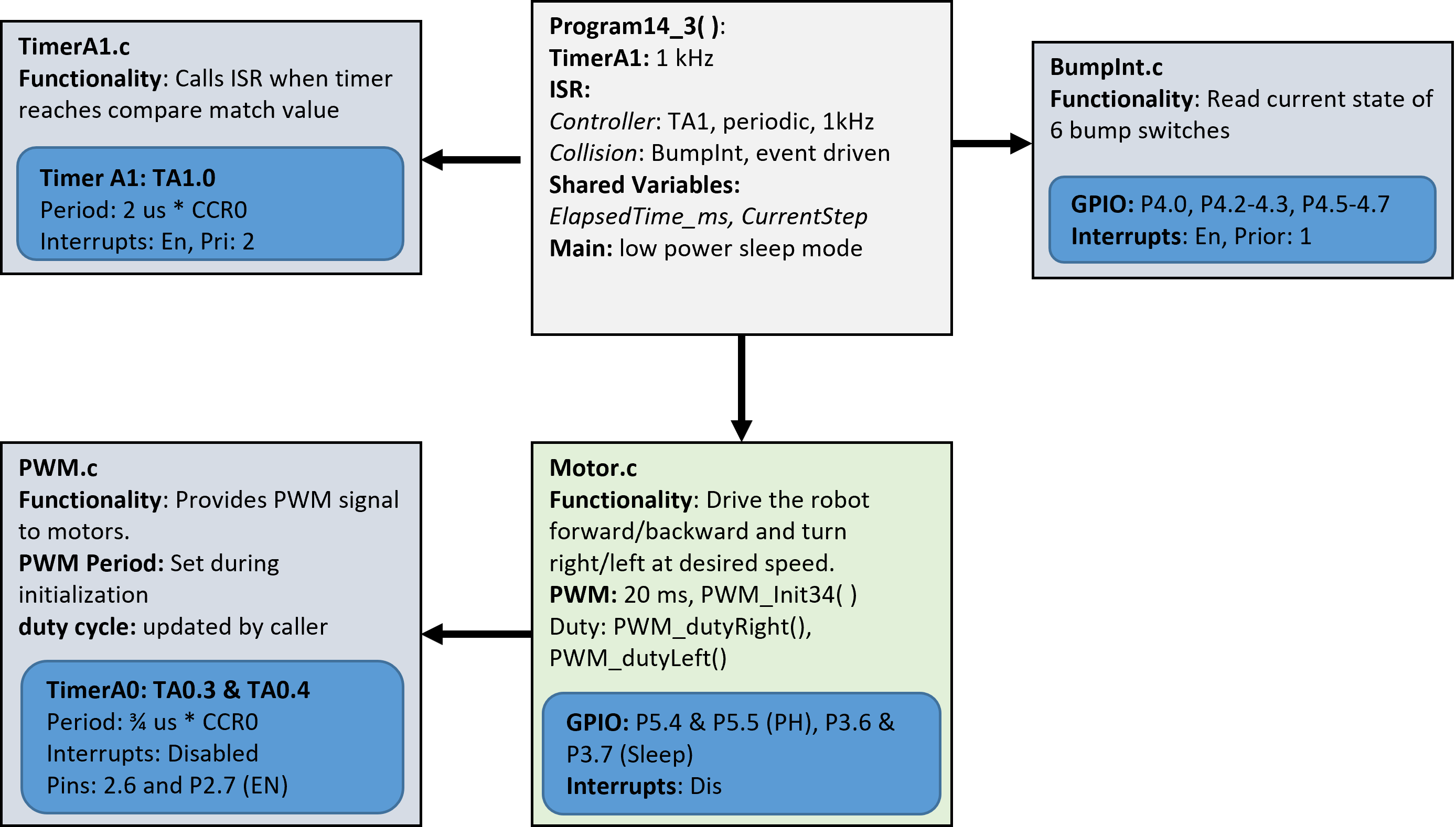
Controller3(),Collision3(), andProgram14_3().As shown in the component block diagram below, there are two interrupts: TimerA1.0 and Port4.

The
Controller3()function should be called byTA1_0_IRQHandler.To make this happen,
TA1_0_IRQHandlermust know the address of theController3()function (function pointer).When you initialize TimerA1 using
TimerA1_Init, you should pass the function pointer as an argument. Then, you need to assign the address of the function to theTimerA1Taskvariable defined at the top ofTimerA1.c.Then, you can call
Controller3()insideTA1_0_IRQHandlerusing the function pointer,TimerA1Task.
Note
TimerA1Task is the address of Controller3, not the function itself. You must add the * symbol to call the function, i.e., (*TimerA1Task)().
Similarly, the
Collision3()functions will be called byPORT4_IRQHandler.To make this happen, you need to pass the address of
Collision3()as an argument toBumpInt_Init.The pointer
BumpTaskinsideBumpInt.cholds the address ofCollision3, and therefore*BumpTaskis theCollision3function itself.So,
(*BumpTask)(Bump_Read())is the same asCollision3(Bump_Read()).
Tip
Collision3(Bump_Read());
is the same as
uint8_t x = Bump_Read();
Collision3(x);
You know \(f(g(x))\) is the same as \(y=g(x)\) followed by \(f(y)\).
Inside
Lab14_RealTimeSystemsMain.c, implement theController3function. Ensure that you do not include any while or for loops inside Controller3, as the function is called every 1 ms. Including loops or delays inside an ISR is highly inefficient and should be avoided.Complete the implementation of
Program14_3().Initial Test (without Bump Sensor Interrupts): Test
Program14_3()without enabling the bump sensor edge-triggered interrupts. The robot should cycle through the three motor commands indefinitely.Implement Collision Handling: Next, implement the
Collisionfunction and test the bump sensors. When a bump sensor is triggered, the robot must stop and restart the set of commands, beginning withMotor_Backward.Final Demo: For the final demonstration, ensure
Program14_3runs the following sequence of commands:Motor_Backward,Motor_TurnRight,Motor_Forward, andMotor_TurnLeft. Upon detecting a collision, the robot should stop and restart the sequence from the beginning. During the demo, explain what you are demonstrating.
Video Credit: C25 Kaitlyn Grimm
🚚 Deliverables#
Deliverable 1#
[6 Points] Demo
Program14_2(), showcasing the count of collisions and the bump data identifying the pressed bump switch. Explain why the count of collisions displayed on the LCD is incorrect.
Deliverable 2#
[6 Points] Demo
Program14_3()running a simple set of commands -Motor_Backward(),Motor_TurnRight(),Motor_Forward(), andMotor_TurnLeft. On a collision, the robot must stop and restart the set of commands. During the demo, explain what you are demonstrating.
Deliverable 3#
[7.5 Points] Push your code to your repository using git. Write comments in your code.
This lab was originally adapted from the TI-RSLK MAX Solderless Maze Edition Curriculum and has since been significantly modified.
