ECE 315 — Block 3, Lesson 14#
Transistors and Digital Logic#
1. What Is a Computer?#
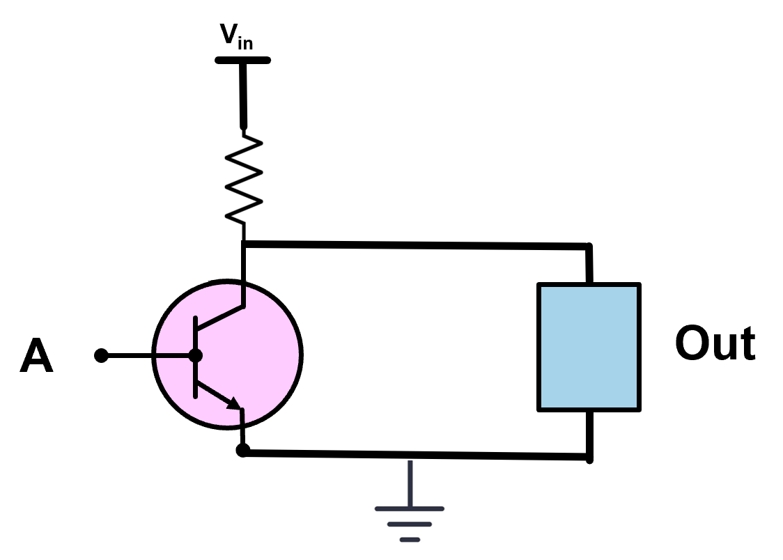
Figure 14-01. Conceptual view of a computer as an input–process–output system.
A computer is a deterministic system that maps inputs to outputs according to predefined logical rules. While modern computers appear complex, their operation reduces to a sequence of logical decisions implemented in hardware. These decisions are not abstract; they are realized using physical electronic components.
All computation can be decomposed into three fundamental functions: logic, arithmetic, and memory. Logic is foundational. Arithmetic operations are constructed from logic, and memory relies on logic to control storage and retrieval. As a result, understanding logic circuits is a prerequisite for understanding how any computer operates.
2. Why Transistors Matter#
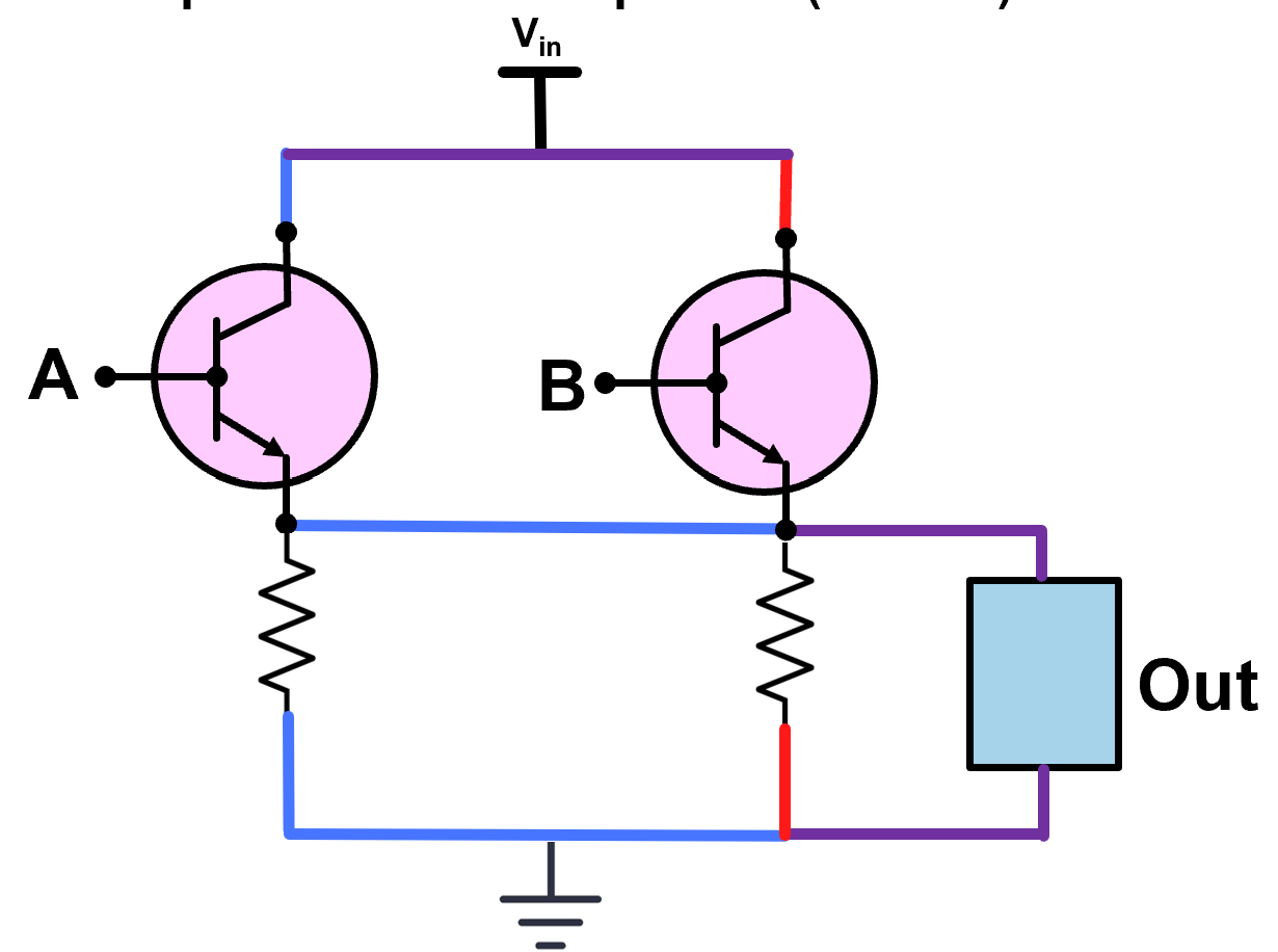
Figure 14-02. Logic circuits constructed from transistors.
At the lowest level, computers are built from transistors. A transistor is an electronic device that can control the flow of current. In digital systems, transistors are used almost exclusively as switches. This switching behavior allows circuits to represent logical states using voltage levels.
Rather than processing continuous signals, digital circuits intentionally restrict transistors to two operating conditions: ON and OFF. These two states form the physical basis for binary logic.
3. Semiconductor Foundations#
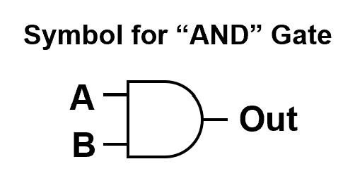
Figure 14-03. N-type and P-type semiconductor regions.
Semiconductors are materials whose electrical properties can be precisely controlled through doping. N-type material contains an excess of electrons, while P-type material contains holes. By arranging these regions strategically, devices can be created that allow or restrict current flow.
This controlled conductivity enables the construction of transistors.
4. Bipolar Junction Transistor Structure#
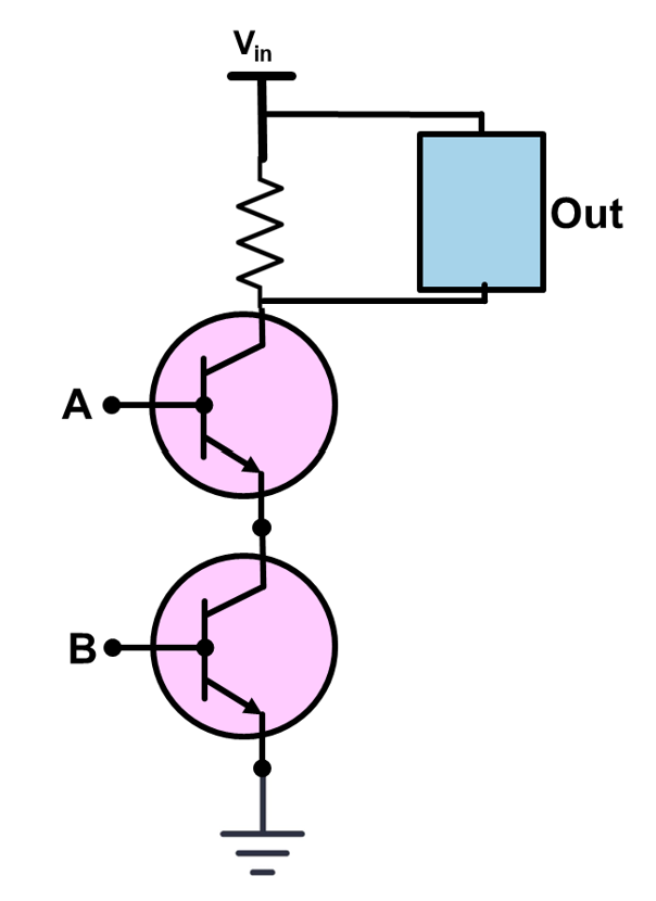
Figure 14-04. NPN and PNP transistor structures.
A bipolar junction transistor (BJT) consists of three regions and terminals: emitter, base, and collector. In an NPN transistor, a small base current allows a much larger collector–emitter current to flow. This current control mechanism enables switching.
While both NPN and PNP devices exist, NPN transistors are commonly used in introductory logic examples due to their intuitive current flow direction.
5. Transistors as Digital Switches#
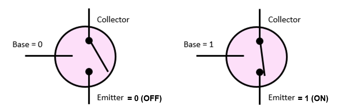
Figure 14-05. Transistor OFF (logic 0) and ON (logic 1) states.
In digital logic, the transistor is deliberately operated outside of its linear region. When the base input is low, the transistor is OFF and no current flows. When the base input is high, the transistor turns ON and conducts.
This behavior maps directly to binary logic: OFF corresponds to 0, and ON corresponds to 1.
6. Truth Tables#
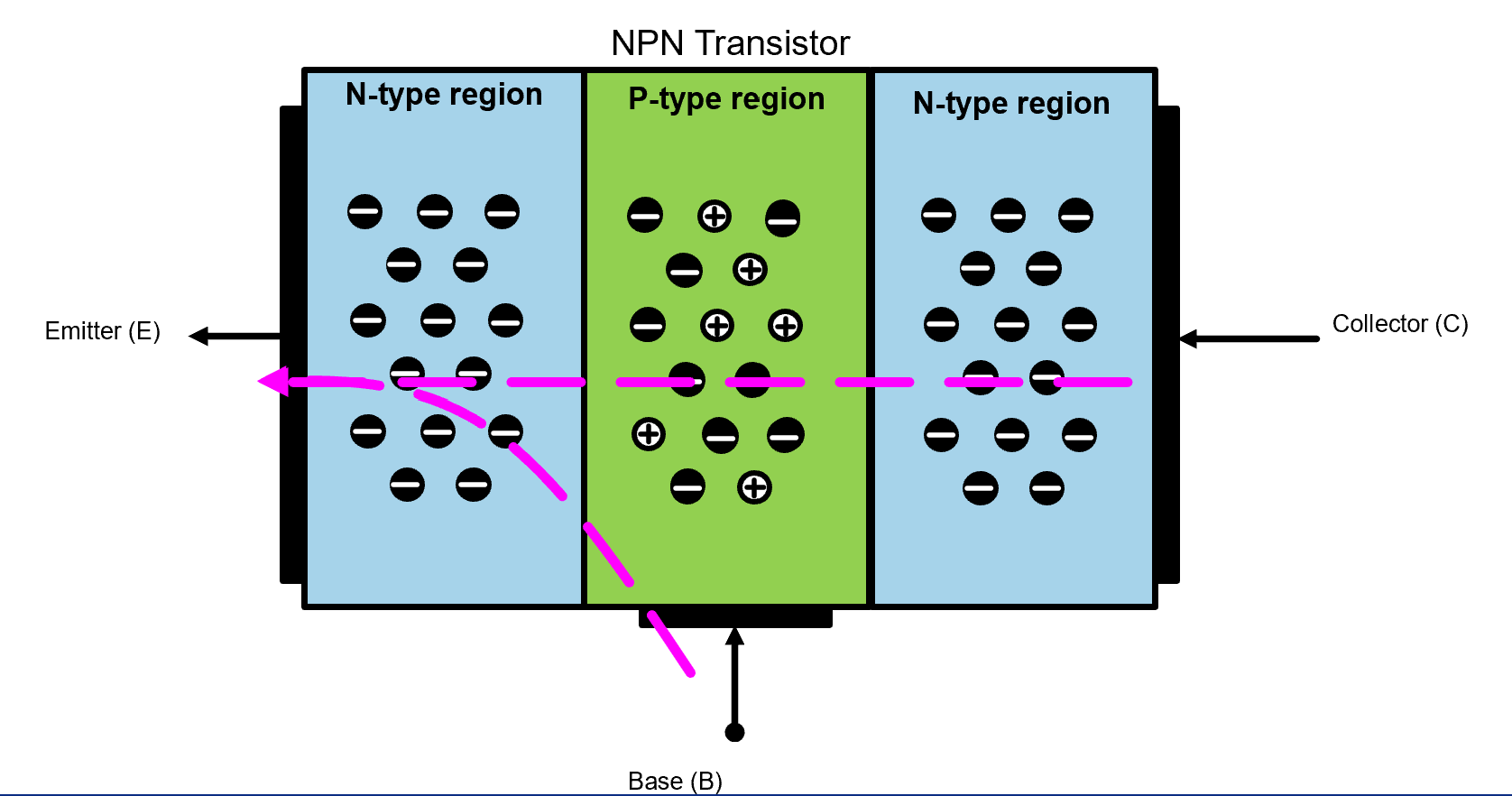
Figure 14-06. Truth tables describing logical behavior.
A truth table defines the output of a logic function for every possible combination of inputs. Truth tables describe what a circuit does, not how it is implemented. Multiple circuit designs may satisfy the same truth table.
Truth tables serve as a contract between logical intent and physical implementation.
7. Logic Gates from Transistors#
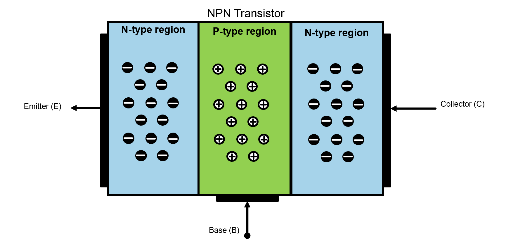
Figure 14-07. AND and OR logic implemented using transistor arrangements.
By arranging transistors in series, an AND function is created: current flows only when all inputs are high. By arranging transistors in parallel, an OR function is created: current flows when any input is high.
These arrangements directly mirror the logical definitions of AND and OR.
8. NOT Gate#
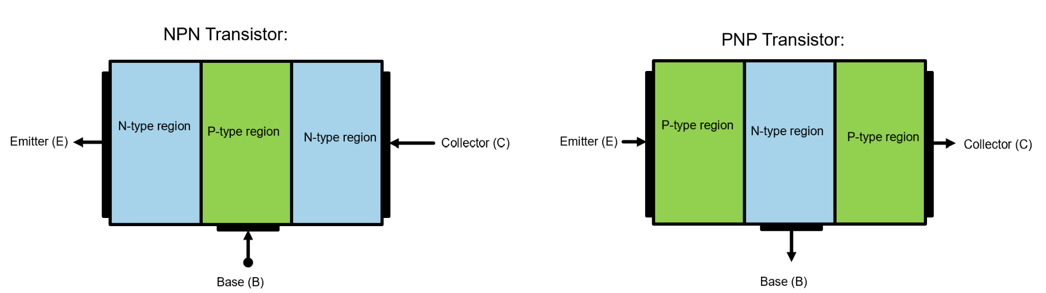
Figure 14-08. NOT gate symbol and inverter behavior.
The NOT gate inverts its input. A high input produces a low output, and vice versa. The NOT gate is fundamental because it enables the construction of more complex logic from simple components.
9. Composing Logic Functions#
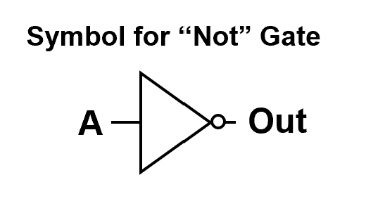
Figure 14-09. Logic composed from multiple gates.
Complex logic functions are built by combining basic gates. Analysis proceeds by identifying intermediate signals and applying truth tables step by step. This structured reasoning approach scales to arbitrarily complex systems.
10. Transistor Count and Design Implications#
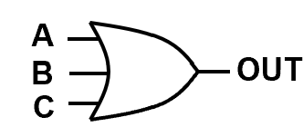
Figure 14-10. Transistor count associated with logic functions.
Each logic gate requires multiple transistors. As systems grow, transistor count directly impacts power consumption, area, and cost. Modern processors contain billions of transistors, making efficiency a primary design concern.
Summary#
Computers operate through logical decision-making
Transistors implement logic as electronic switches
Truth tables define behavior independently of implementation
Logic gates are built by arranging transistors
Complexity scales through structured composition