Practice Problems#
Answer the following questions about the circuit below.
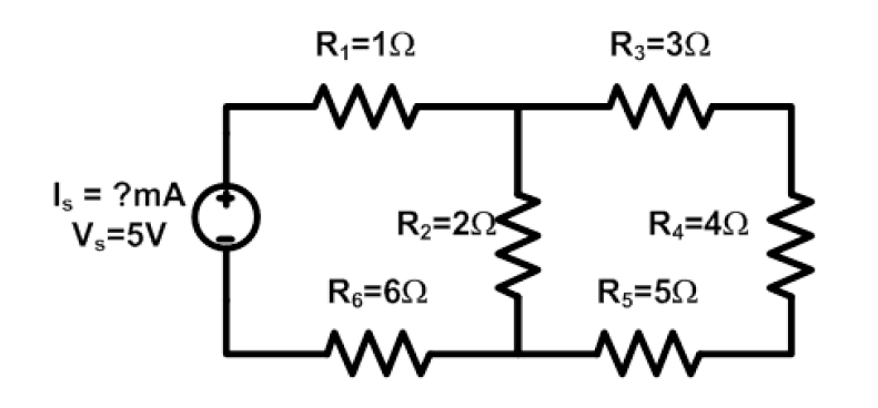
a. Find \(I_S\).
b. Find the power consumed by \(R_2\).
Find \(R_{EQ}\), \(I_S\), \(P_2\), and \(P_{Total}\) for the following circuit.
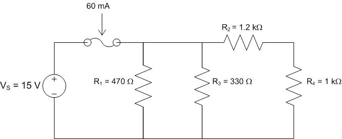
Find the equivalent resistance of the following circuit and determine if the fuse rating is high enough.
Determine the appropriately sized resistor so the voltage across the load is 45 V.
For resistors in series, a bigger resistor drops more voltage than a smaller resistor.
(a) True (b) False
For resistors in series, more current flows through the bigger resistor.
(a) True (b) False
In a current divider, the greater current always flows through the smaller resistor.
(a) True (b) False
For resistors in parallel, the equivalent resistance is always less than the smallest resistor.
(a) True (b) False
What is the purpose of a fuse? Choose all that apply.
(a) To keep a circuit from working under normal conditions.
(b) To allow a circuit to work under normal conditions.
(c) To protect the wiring of a circuit.
(d) To break the circuit during excessive currents.
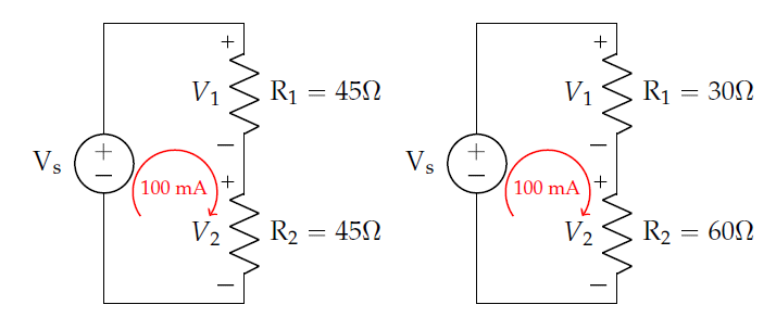
Solve for the unknown parameter(s) in each of the following circuits.
a. Circuit #1
b. Circuit #2
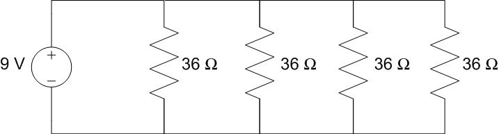
Four 36 Ω light bulbs are connected in parallel to a 9 V battery, as shown. How much power does the battery produce?
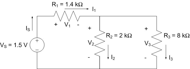
A SATCOM control module is modeled as the circuit below. Which of the following are true? Select all that apply.
a. \(I_1 = I_2\)
b. \(V_2 = V_3\)
c. \(I_2 > I_3\)
d. \(V_1 + V_3 = V_S\)
The proposed arming circuitry of an experimental munition is modeled as the following resistive circuit. Answer the questions below.
\(R_1 = 600\ \Omega\), \(R_2 = 300\ \Omega\), \(R_3 = 400\ \Omega\), \(R_4 = 500\ \Omega\)
a. What is \(R_{eq}\) as seen by the source \(V_S\)?
b. What is the source voltage \(V_S\)?
c. How much power is dissipated in \(R_2\)?
d. What is the voltage across \(R_4\)?
The circuit below shows a variable power supply capable of providing up to 50 V. Assume each bulb is modeled by a 3 Ω resistor.
a. Calculate the maximum voltage setting on the power supply before the fuse blows.
b. Calculate the voltage across each light bulb assuming maximum current flow (just before the fuse blows).
The circuit below shows a television represented by a 5 kΩ load requiring 50 V to operate, connected to a 120 V source.
a. Given only 2 kΩ and 3 kΩ resistors, how could you create a voltage adapter to make this circuit work?
b. Given only 2 kΩ resistors, how could you create a voltage adapter to make this circuit work?