Practice Problems (KEY)
Problem 1
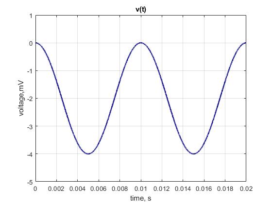
(a) \(v(t) = -2 + 2\cos(360°\cdot 100\,\text{Hz}\cdot t)\,\text{mV}\)
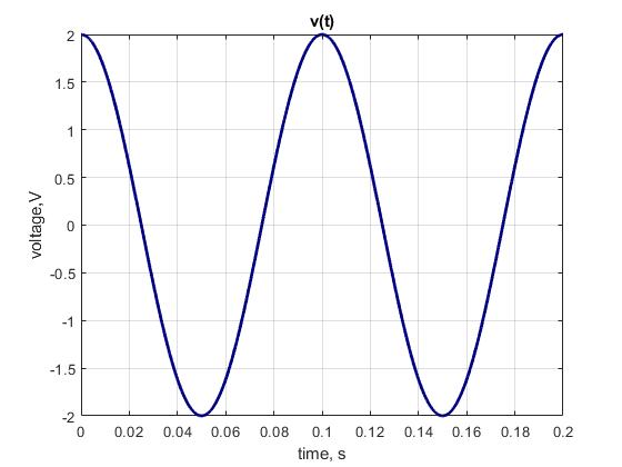
(b) \(v(t) = 2\cos(360°\cdot 10\,\text{Hz}\cdot t)\,\text{V}\)
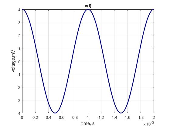
(c) \(v(t) = 4\cos(360°\cdot 1\,\text{kHz}\cdot t)\,\text{mV}\)
(d)
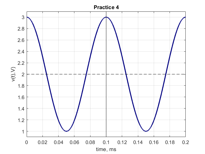
\[v(t) = 2\,\text{V} + \cos(360°\cdot 10\,\text{kHz}\cdot t)\,\text{V}\]
(e)
\[v(t) = \cos(360°\cdot 400\,\text{kHz}\cdot t)\,\text{mV}\]
Problem 2
\[i_X(t) = \frac{v_S(t)}{R_{\text{eq}}} = \frac{4 + 8\cos(360°\cdot 10\,\text{kHz}\cdot t)}{400\,\Omega}\]
\[\boxed{i_X(t) = 10 + 20\cos(360°\cdot 10\,\text{kHz}\cdot t)\,\text{mA}}\]
Problem 3
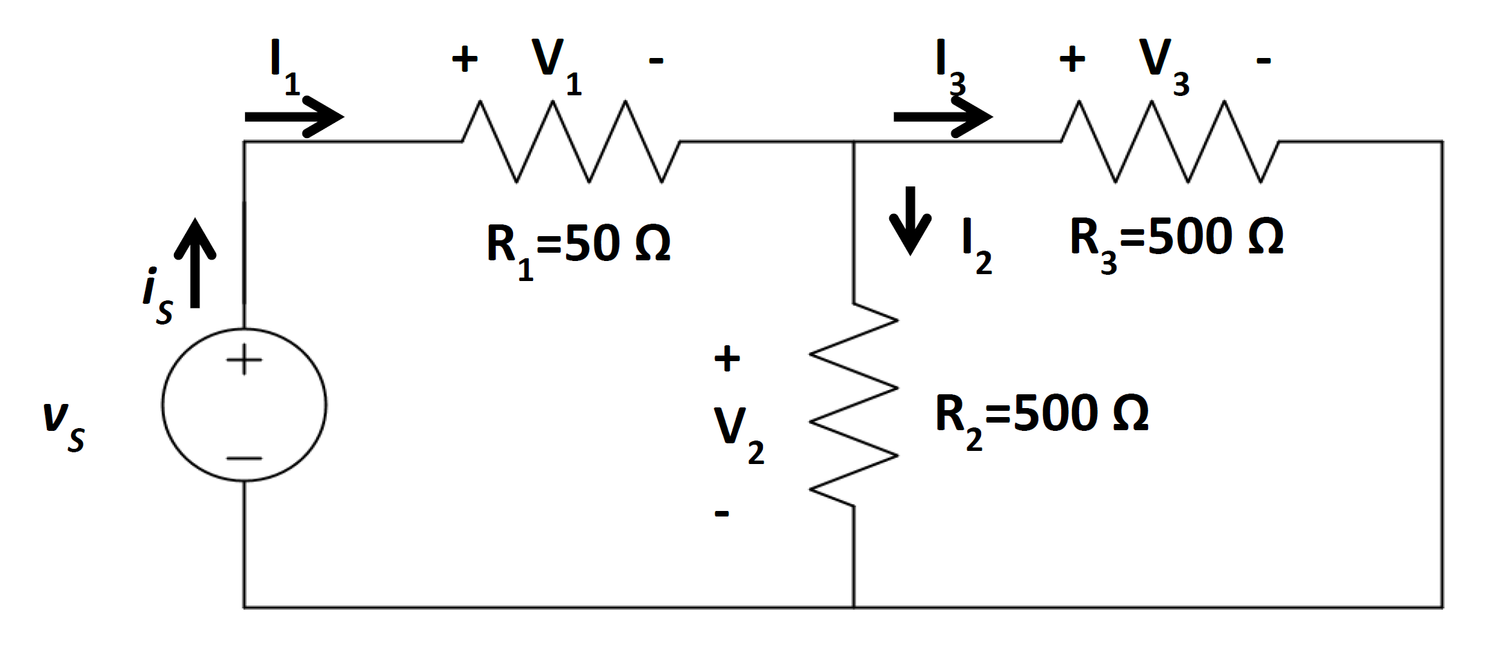
\[R_{\text{eq}} = \left(\frac{1}{500\,\Omega} + \frac{1}{500\,\Omega}\right)^{-1} + 50\,\Omega = 300\,\Omega\]
\[I_S = \frac{V_S}{R_{\text{eq}}} = \frac{1.5\,\text{V}}{300\,\Omega} = 5\,\text{mA}\]
\[P_{\text{tot}} = I_S V_S = (5\,\text{mA})(1.5\,\text{V}) = \boxed{7.5\,\text{mW}}\]
Problem 4
\[V_{\text{RMS}} = \frac{2.12}{\sqrt{2}} = 1.5\,\text{V}_{\text{RMS}} \qquad I_{\text{RMS}} = \frac{V_{\text{RMS}}}{R_{\text{eq}}} = \frac{1.5\,\text{V}}{300\,\Omega} = 5\,\text{mA}\]
\[P_{\text{AVG}} = V_{\text{RMS}} I_{\text{RMS}} = (1.5\,\text{V})(5\,\text{mA}) = \boxed{7.5\,\text{mW}}\]
The power consumed is the same as Problem 3. A DC source of 1.5 V and an AC source of 1.5 V\(_\text{RMS}\) deliver identical average power to the same resistive load.
Problem 5
a. s — \(\frac{1}{\text{Hz}} = \frac{1}{1/\text{s}} = \text{s}\)
Problem 6
d. \(9\,\text{V}_{\text{RMS}}\) — The 9 V DC source delivers power \(P = V^2/R\). An AC source delivers the same average power when \(V_{\text{RMS}} = 9\,\text{V}\).
Problem 7
(a)
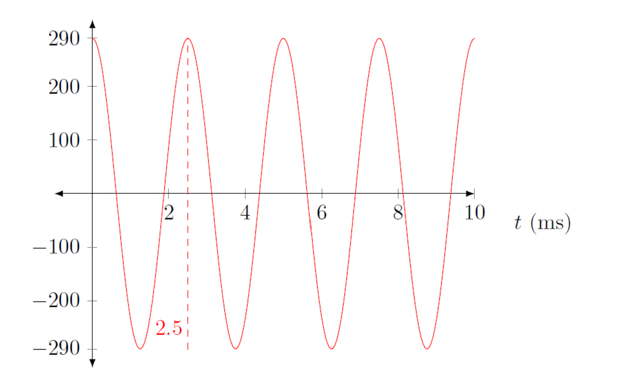
(b)
\[V_{\text{RMS}} = \frac{A}{\sqrt{2}} = \frac{290\,\text{V}}{\sqrt{2}} = \boxed{205\,\text{V}_{\text{RMS}}}\]
Problem 8
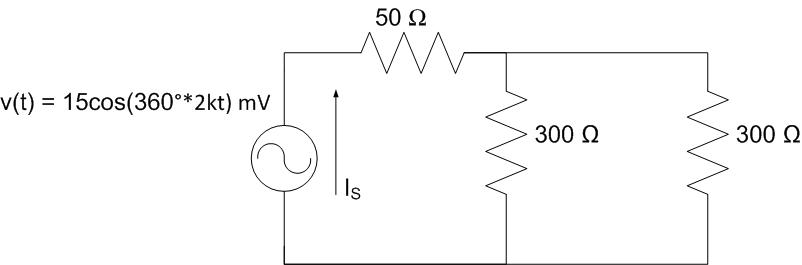
\[R_{\text{EQ}} = (300\,\Omega \parallel 300\,\Omega) + 50\,\Omega = 200\,\Omega\]
\[I_S(t) = \frac{v(t)}{R_{\text{EQ}}} = \frac{15\cos(360°\cdot 2\,\text{kHz}\cdot t)\,\text{mV}}{200\,\Omega} = \boxed{75\cos(360°\cdot 2\,\text{kHz}\cdot t)\,\mu\text{A}}\]
Period: \(T = \frac{1}{2000\,\text{Hz}} = 500\,\mu\text{s}\)
Problem 9
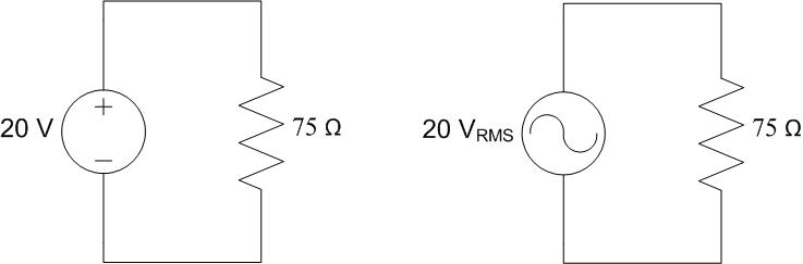
Both sources produce identical average power. A 20 V DC source and a 20 V\(_\text{RMS}\) AC source deliver the same average power to a resistive load, since RMS voltage is the DC-equivalent for power calculations.
\[P = \frac{V^2}{R} = \frac{(20\,\text{V})^2}{75\,\Omega} = \frac{(20\,\text{V}_{\text{RMS}})^2}{75\,\Omega} = 5.33\,\text{W}\]
Problem 10
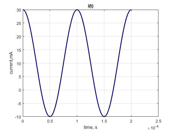
\[R_{\text{eq}} = \left(\frac{1}{6\,\Omega} + \frac{1}{10\,\Omega} + \frac{1}{8\,\Omega}\right)^{-1} = 2.553\,\Omega\]
\[I_1(t) = \frac{R_{\text{eq}}}{6\,\Omega}\,i(t) = \frac{2.553}{6}\left(11.75\cos(360°\cdot 50\,\text{Hz}\cdot t)\right) = 5\cos(360°\cdot 50\,\text{Hz}\cdot t)\,\text{A}\]
\[\boxed{v_1(t) = I_1(t)\cdot 6\,\Omega = 30\cos(360°\cdot 50\,\text{Hz}\cdot t)\,\text{V}}\]
Problem 11
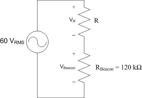
Using the voltage divider equation solved for \(R_{\text{adapter}}\):
\[V_{\text{fan}} = V_S \frac{R_{\text{fan}}}{R_{\text{adapter}} + R_{\text{fan}}} \implies R_{\text{adapter}} = R_{\text{fan}} \frac{V_S - V_{\text{fan}}}{V_{\text{fan}}}\]
\[R_{\text{adapter}} = 150\,\Omega \cdot \frac{120\,\text{V}_{\text{RMS}} - 90\,\text{V}_{\text{RMS}}}{90\,\text{V}_{\text{RMS}}} = \boxed{50\,\Omega}\]