Practice Problems (KEY)
Problem 1
\[P_{\text{gen}} = I_S V_S = 18 \times 190 = \boxed{3.42\,\text{kW}}\]
(Block diagram and breaker labels shown above. A, B, C are on the 190 V bus; X, Y, Z are on the 40 V bus.)
Problem 2
(a) \(a = \frac{V_1}{V_2} = \frac{35}{205} = \boxed{0.171}\)
(b)
\[P_{\text{flaps,in}} = \frac{11{,}190\,\text{W}}{0.62} = 18\,\text{kW} \implies I_{\text{Flaps}} = \frac{18{,}000}{205} = 88\,\text{A}\]
\[I_C = 88 + 12 + 12 = 112\,\text{A} \implies \text{CB}_C = 112 \times 1.1 = 123\,\text{A} \rightarrow \boxed{125\,\text{A}}\]
\[P_B = \frac{(205\,\text{V})(112\,\text{A})}{0.8} = 28.7\,\text{kW} \implies I_B = \frac{28{,}700}{32} = 897\,\text{A} \implies \text{CB}_B \rightarrow \boxed{1\,\text{kA}}\]
\[I_A = 5 + 2.3 + 897 = 904\,\text{A} \implies \text{CB}_A = 904 \times 1.1 = 994\,\text{A} \rightarrow \boxed{1\,\text{kA}}\]
(c) \(P_S = V_S I_A = 32 \times 904 = \boxed{28.9\,\text{kW}}\)
Problem 3
False — Buses deliver power to devices connected in parallel, so all devices share the same bus voltage.
Problem 4
True — A circuit breaker opens (trips) when current exceeds its rating, just like a fuse. The key difference is that a circuit breaker can be reset, while a fuse must be replaced.
Problem 5
(a) \(a = \frac{160}{50} = \boxed{3.2}\)
(b)
\[I_D = 3.5\,\text{A} \implies \text{CB}_D = 3.5 \times 1.1 = 3.85\,\text{A} \rightarrow \boxed{4\,\text{A}}\]
\[I_C = 3.5 + 4.5 = 8\,\text{A} \implies \text{CB}_C = 8 \times 1.1 = 8.8\,\text{A} \rightarrow \boxed{9\,\text{A}}\]
\[I_B = \frac{I_C}{a} = \frac{8}{3.2} = 2.5\,\text{A} \implies \text{CB}_B = 2.5 \times 1.1 = 2.75\,\text{A} \rightarrow \boxed{3\,\text{A}}\]
\[I_A = 2.5 + 4 + 6 + 2.5 = 15\,\text{A} \implies \text{CB}_A = 15 \times 1.1 = 16.5\,\text{A} \rightarrow \boxed{16.5\,\text{A}}\]
Problem 6
(a)
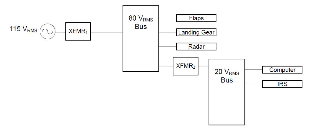
\[a_{\text{XFMR1}} = \frac{115}{80} = \boxed{1.4375} \qquad a_{\text{XFMR2}} = \frac{115}{20} = \boxed{5.75}\]
(b)
\[I_{20\,\text{V}} = 2 + 5 = 7\,\text{A} \implies I_{1,\text{XFMR2}} = \frac{7}{5.75} = 1.21\,\text{A}\]
\[I_{80\,\text{V}} = 5 + 8 + 4 = 17\,\text{A} \implies I_{1,\text{XFMR1}} = \frac{17}{1.4375} = 11.8\,\text{A}\]
\[I_S = 1.21 + 11.8 = 13\,\text{A}\]
\[P_{\text{ALT}} = I_S V_S = (13)(115) = \boxed{1.495\,\text{kW}}\]
Verification: \(P_{\text{ALT}} = 80(5+8+4) + 20(2+5) = 1360 + 140 = 1500\,\text{W} \approx 1.5\,\text{kW}\) ✓
Problem 7
(a)
\[a_{\text{XFMR2}} = \frac{80}{20} = \boxed{4} \qquad a_{\text{XFMR1}} = \frac{115}{80} = \boxed{1.4375}\]
(b)
\[I_{20\,\text{V}} = 2 + 5 = 7\,\text{A} \implies I_{1,\text{XFMR2}} = \frac{7}{4} = 1.75\,\text{A}\]
\[I_{80\,\text{V}} = 5 + 8 + 4 + 1.75 = 18.75\,\text{A} \implies I_{1,\text{XFMR1}} = \frac{18.75}{1.4375} = 13\,\text{A} = I_S\]
\[P_{\text{ALT}} = I_S V_S = (13)(115) = \boxed{1.495\,\text{kW}}\]
Problem 8
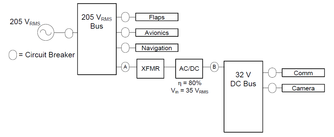
Turns ratio:
\[a = \frac{V_1}{V_2} = \frac{205}{35} = \boxed{5.86}\]
Breaker B (DC side — Comm + Camera):
\[I_B > 4 + 5 = 9\,\text{A} \rightarrow \boxed{10\,\text{A}}\]
Breaker A (AC side — transformer primary):
\[P_{\text{DC}} = (32\,\text{V})(4 + 5\,\text{A}) = 288\,\text{W}\]
\[P_{\text{in,ACDC}} = \frac{288}{0.8} = 360\,\text{W}\]
\[I_{\text{XFMR}} = \frac{360\,\text{W}}{205\,\text{V}_{\text{RMS}}} = 1.75\,\text{A} \implies \text{CB}_A = 1.75 \times 1.1 = 1.925\,\text{A} \rightarrow \boxed{\approx 2\,\text{A}}\]
Problem 9
Not valid. The added transformer is connected to a DC bus, but transformers require AC to operate (they rely on a changing magnetic field to transfer power). With DC input the transformer will not transfer power, and the 5 V bus will receive no power.
Problem 10
10–13 breakers should be added:
Per-load protection (required): one breaker per load on the 60 V and 25 V buses → 8 breakers
Bus-level protection (recommended): one upstream breaker per bus → +2 breakers (10 total)
Additional isolation (optional): breakers between XFMR2 and the ADC and on either side of the transformers → up to +3 more (13 total)
Baseline: 10 breakers Optimal: 13 breakers