Practice Problems (KEY)#
What components make up a DRAM bit cell?
A DRAM bit cell consists of:
One (1) transistor
One (1) capacitor
This structure is commonly referred to as a 1T1C cell (one-transistor, one-capacitor).
The capacitor stores the bit as electrical charge (charged = 1, discharged = 0), while the transistor acts as an access switch that connects the capacitor to the bitline during read and write operations.
Explain why DRAM exhibits slower access times than SRAM.
DRAM stores each bit as charge on a capacitor. Because real capacitors are not ideal, that charge gradually leaks over time.
As a result, DRAM cells must be periodically refreshed (rewritten) to restore the stored charge. Additionally, reading a DRAM cell is a destructive operation—the stored charge is disturbed during the read and must be rewritten afterward.
These refresh and restore operations increase access latency, making DRAM slower than SRAM.
Which type of memory is non-volatile?
Non-volatile memory retains stored data even when power is removed from the system.
In other words, if you power off your computer, non-volatile memory preserves its contents.
Examples include:
Read-Only Memory (ROM)
Flash Memory
Solid-State Drive (SSD) storage
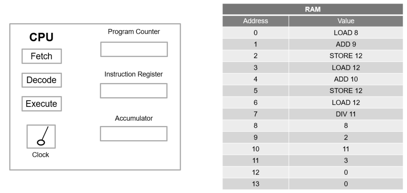
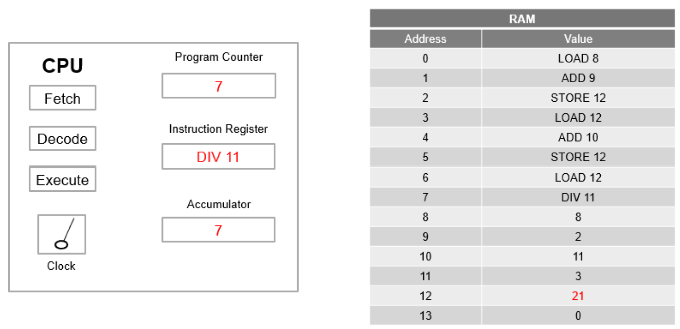
The program shown below calculates the average of three numbers. After eight CPU cycles have executed, determine the values of the Instruction Register (IR), the accumulator, and RAM address 12.
Program Instructions#
Address |
Instruction |
|---|---|
0 |
LOAD 8 |
1 |
ADD 9 |
2 |
STORE 12 |
3 |
LOAD 12 |
4 |
ADD 10 |
5 |
STORE 12 |
6 |
LOAD 12 |
7 |
DIV 11 |
Data values: RAM[8] = 8, RAM[9] = 2, RAM[10] = 11, RAM[11] = 3
Cycle 1 — LOAD 8: ACC ← 8
Cycle 2 — ADD 9: ACC ← 8 + 2 = 10
Cycle 3 — STORE 12: RAM[12] ← 10
Cycle 4 — LOAD 12: ACC ← 10
Cycle 5 — ADD 10: ACC ← 10 + 11 = 21
Cycle 6 — STORE 12: RAM[12] ← 21
Cycle 7 — LOAD 12: ACC ← 21
Cycle 8 — DIV 11: ACC ← 21/3 = 7
Final State After 8 Cycles:
IR = DIV 11
Accumulator = 7
RAM[12] = 21
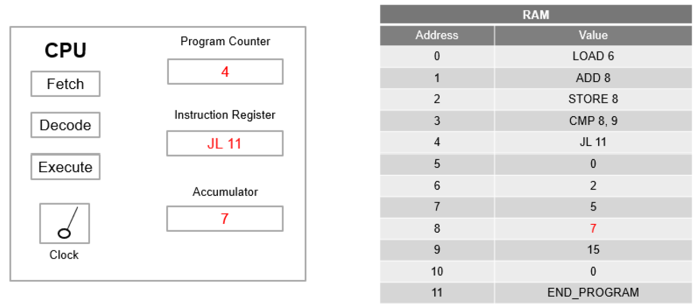
The assembly program shown below compares two numbers. After five CPU cycles have executed, determine the values of the Program Counter (PC), Instruction Register (IR), accumulator, and RAM address 8.
Additionally, determine the values of the Program Counter (PC) and Instruction Register (IR) at the beginning of the sixth CPU cycle.
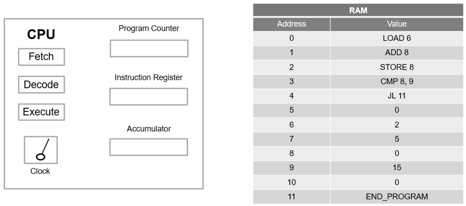
Cycle 1 — LOAD 6: ACC ← RAM[6] = 2
Cycle 2 — ADD 8: ACC ← 2 + 5 = 7 (RAM[8] initially = 5)
Cycle 3 — STORE 8: RAM[8] ← 7
Cycle 4 — CMP 8, 9: Compare RAM[8]=7 with RAM[9]=15; since 7 < 15, “less than” condition is true.
Cycle 5 — JL 11: Jump condition satisfied (7 < 15); PC will transfer to 11.
Final State After 5 Cycles:
PC = 4
IR = JL 11
Accumulator = 7
RAM[8] = 7
Beginning of the 6th Cycle:
PC = 11
IR = END_PROGRAM