Lesson 29 – Modulation 2#
Learning Outcomes
Analyze AM modulators in the frequency domain for both sinusoidal and non-sinusoidal inputs.
Calculate the bandwidth of an AM signal.
Describe block diagram Frequency Domain Multiplexing (FDM) systems.
Analyze FDM systems in the frequency domain.
Modulation 2#
AM with More Than One Frequency#
Although it is instructive to consider how to use a single frequency as a message signal, it is not very practical. In fact, most systems want to send information containing a bandwidth of frequencies. Any communications system, for example, wants to ensure it can at least use data in the audible range (20 Hz – 22 kHz) as its message signal.
Everything up to this point still applies to a message signal with more than one frequency. For example, consider the following modulation system:
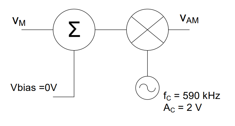
Fig. 1. AM modulation system with a multi-frequency message signal: \(v_m(t)\) contains three components at 1 kHz, 3 kHz, and 5 kHz.
Where \(v_m(t)\) is now:
In this case, determining the time domain representation of the output signal (\(v_{AM}\)) is overly complicated. Even using the distributive law to write the equation of the output signal is overly tedious. However, it is perfectly feasible to draw this signal in the frequency domain if we recall that each frequency in the message signal produces two frequencies in the output signal:
One at \(f_c + f_m\)
One at \(f_c - f_m\)
The amplitude of each frequency is:
So, the example above produces six frequencies in the output.
Fig. 2. Frequency-domain output of the multi-frequency AM system: six sidebands symmetric about \(f_c = 590\) kHz with amplitudes 2, 1, and 6 V.
First, notice how the spectrum is symmetric around the carrier frequency, \(f_c\).
The frequencies to the right of the carrier are:
\(590k + 1k = 591k\ \text{Hz}\)
\(590k + 3k = 593k\ \text{Hz}\)
\(590k + 5k = 595k\ \text{Hz}\)
The amplitudes are:
The frequencies to the left are mirror images about \(f_c\) with identical amplitudes.
AM Spectrum Construction Steps#
Add the carrier frequency to each message frequency.
Compute amplitudes using \(\frac{A_m A_c}{2}\).
Reflect the results about the carrier frequency.
Bandwidth#
Bandwidth is the range of frequencies used to transmit a signal.
For this signal:
The bandwidth of an AM signal is always:
AM Signal Bandwidth
Digital Modulation#
The carrier must be sinusoidal, but the message can be analog or digital.
Amplitude Shift Keying (ASK)#
Binary 0 → low amplitude (0 V)
Binary 1 → high amplitude (e.g., 5 V)
Frequency Shift Keying (FSK)#
Binary 0 → one frequency
Binary 1 → another frequency
Fig. 3. Digital modulation types: Amplitude Shift Keying (ASK) and Frequency Shift Keying (FSK) encode binary data in the carrier’s amplitude or frequency.
Frequency Division Multiplexing (FDM)#
Two approaches to multiplexing:
Time Division Multiplexing (TDM): Signals share time
Frequency Division Multiplexing (FDM): Signals share frequency spectrum
FDM allows multiple signals to be transmitted simultaneously by assigning each a unique frequency band.
Fig. 4. Frequency Division Multiplexing (FDM): multiple signals are assigned unique frequency bands so they can share the same channel simultaneously.
FDM Process#
Band-limit each signal (using LPFs)
Shift each signal to a unique frequency band (modulation)
Add signals together
The result is a composite signal with non-overlapping spectra.
Fig. 5. FDM composite output spectrum: three signals occupy non-overlapping frequency bands after band-limiting, modulation, and combining.
Low-pass filters ensure signals do not overlap by limiting bandwidth.
Example Problem 1
Two music signals are multiplexed as shown below. Graph the output in the frequency domain.
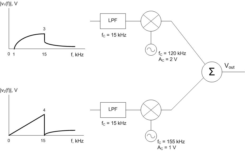
Fig. 6. Block diagram for Example Problem 1: two music signals pass through LPFs, then are shifted to separate carrier frequencies (120 kHz and 155 kHz) for FDM.
Understand: We are multiplexing signals in the frequency domain.
Note: \(f_c\) represents:
Filter cutoff frequency (LPFs)
Carrier frequency (modulators)
Identify Key Information:
Knowns: Input frequencies, LPF cutoff, carrier frequencies
Unknowns: Output spectrum
Assumption: System supports full bandwidth
Plan:
Follow each signal path
Apply filtering
Apply modulation
Combine results
Solve: First signal after LPF:
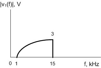
Fig. 7. Example Problem 1 — first music signal after the low-pass filter: band-limited spectrum ready for modulation.
Second signal after LPF:
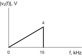
Fig. 8. Example Problem 1 — second music signal after the low-pass filter: band-limited spectrum ready for modulation.
Then:
Shift first signal by \(120k\)
Reflect about carrier
Shift second signal by \(155k\)
Reflect about carrier
LPFs ensure no spectral overlap.
Answer:
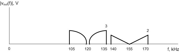
Fig. 9. Example Problem 1 answer: FDM output spectrum with both music signals occupying non-overlapping bands centered at 120 kHz and 155 kHz.
Key Takeaways#
AM with multi-frequency messages. When the message contains multiple frequency components, each frequency produces its own pair of sidebands symmetric about the carrier frequency, with amplitudes scaled by \(A_m A_c / 2\).
AM signal bandwidth. The bandwidth of an AM signal is always twice the highest message frequency: \(BW = 2 f_{m,\text{max}}\), regardless of how many frequency components the message contains.
Digital modulation. Amplitude Shift Keying (ASK) and Frequency Shift Keying (FSK) are digital variants of AM and FM that encode binary data by switching the carrier’s amplitude or frequency between two discrete states.
Frequency Division Multiplexing (FDM). FDM allows multiple signals to share a single channel simultaneously by assigning each signal a unique frequency band through modulation to different carrier frequencies.
Low-pass filtering before FDM. Each signal must be band-limited with a low-pass filter before modulation to prevent its sideband spectrum from overlapping with adjacent signals in the FDM output.
Frequency-domain analysis. Analyzing AM and FDM systems in the frequency domain — tracking amplitude and frequency of each component — is far more efficient than working through the time-domain algebra when the message has multiple frequencies.
Changing broadcast frequency. The output spectrum of an AM signal shifts with the carrier frequency, so changing the carrier frequency simply relocates the entire signal to a different part of the RF spectrum without altering its shape.