Lesson 9 – Power Generation and Transmission#
Learning Outcomes
Explain how a DC motor converts electricity to mechanical power and how a generator converts mechanical power to electricity.
Identify the major sources of loss in a motor.
Calculate the efficiency of a system and how it affects the power consumed by the load.
Identify the major sources of energy for the US power grid, explain how they operate, and compare their strengths and weaknesses.
Describe how transformers work, what they do, and how they are used in power transmission systems.
Given a transformer’s primary and secondary electrical values (voltage and current), calculate the required turns ratio, and vice versa.
Calculate the efficiency and source voltage of a power transmission system with one or more transformers.
Power Generation and Motors#
We’re fortunate to live in a society that has electrical power at our disposal. The simplicity of plugging a device into an outlet makes it all too easy to take this for granted. However, this is a very modern convenience made possible by many advancements at the end of the 19th century and throughout the 20th century. The most notable advancements were those in generators and motors at the end of the 19th century by the electrical engineer Nikola Tesla[1] and others that paved the way for reliable and cheap electrical power. Due to the importance of motors and generators in power generation and distribution, we will cover the principles of motors and generators before discussing their efficiencies and various sources of electrical power. Interestingly, generators are not restricted to powerplants; generators are attached to the turbines in many modern aircraft and provide all of the usable electricity for the aircraft and its passengers.
Motors and Generators#
Motors allow us to convert electrical energy into rotational mechanical energy. They consume electrical energy and output rotational mechanical energy in the form of a rotating shaft which can do work. From there, mechanical engineers can convert it into all sorts of other mechanical work such as moving a vehicle, raising an elevator, or pumping water. Generators simply reverse this process: mechanical energy is used to turn a shaft, which outputs electrical energy as it rotates.
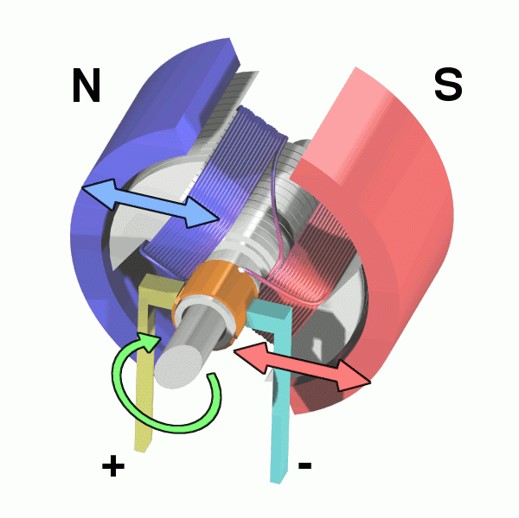
Fig. 1. A 3D cross-section of a DC motor.
The basic principles of motors are fairly straightforward. When two magnets are near each other, they naturally want to line up so the “North” end is near the “South” end of the other. To leverage this effect, we place a magnet on a shaft that can rotate, inside another magnet that stays stationary. In this case, the rotating magnet, called the rotor, will perform work in rotating to align itself with the outer magnet, called the stator. This can be visualized in Figure 1 and Figure 2.
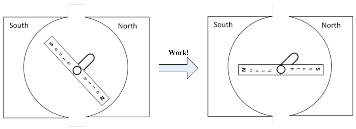
Fig. 2. A motor consisting of a rotor and stator.
According to Ampere’s Law, a wire with an electric current going through it creates a magnetic field around it. Furthermore, if we coil that wire around a ferromagnetic material, such as a block of iron, it strengthens the field and makes a magnet with a North and South pole. In fact, it is possible to make a very simple electromagnet by wrapping a wire around a large nail and then connecting the wire to a battery. However, the most useful thing about electromagnets in motors is this: if the direction of the current is reversed, the polarity of the magnet switches. This is shown in Figure 3 below.
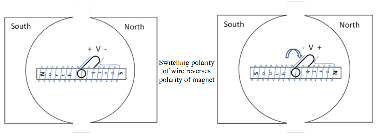
Fig. 3. A DC motor with permanent magnet stators and an electromagnetic rotor.
When we reverse the polarity, the North and South poles on the rotor switch sides, causing a force that tries to place the rotor in the opposite position. If we properly time the polarity reversal while the rotor is in motion, the rotor tries to align to a new position, creating torque as it tries to reach the new position. In essence, a DC motor turns by changing the poles on the rotor while the poles on the stator are held constant. This effect is visualized in Figure 3.
In order to properly coordinate the timing of this effect, a DC motor uses a commutator and brushes to both transfer the electricity and reverse the polarity. A commutator is a metal strip on the outside of the shaft which provides metal conductivity from the rotating shaft to the coils on the rotor. Brushes are metal strips (or a roller) that touch the commutator and provide the electric source. While not completely accurate, think of the commutator and brushes as the voltage source (+ V − and − V +) in Figure 3. Every time the shaft completes half a rotation, the commutators switch which charged brush (positive or negative) they are connected to. Therefore, the current is reversed and so is the polarity of the electromagnet, and the motor continues to spin. The brushes, commutator, and rotor of a DC motor are shown in Figure 4.
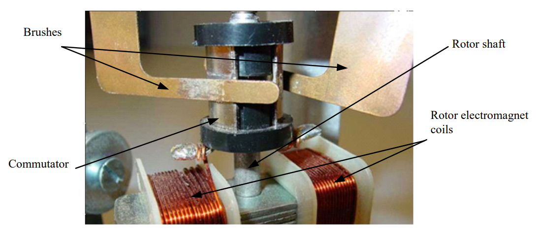
Fig. 4. A view of the commutator and brushes.
Motors can work on either AC or DC electricity, and within each of those groups, there are several different designs. However, all are based on the concept of magnetic fields trying to align.
One last note on motors: as with all electrical machines, they are rated in how much work they can do per unit time. However, while electrical engineers use Watts to rate power, motors are rated in horsepower. Horsepower was used for motors and engines before electricity was discovered, and the convention stuck. The conversion is one horsepower (hp) to 745.7 Watts.
Efficiency (\(\eta\))#
As we prepare to move into more real-world scenarios, we need to introduce the concept of efficiency. Efficiency is a measure of how much power is wasted when we use electricity to do useful tasks. If we don’t waste any power, or we use all the power we produce, the efficiency of our system is 100%. If we only waste a little power, then our efficiency is high (usually, above 95%). If we waste a lot of power, our efficiency is low. There are a number of ways to calculate efficiency; the one you use depends on what you know about the system at hand.
Efficiency
In the above equation, \(P_{OUT}\) or \(P_{USEFUL}\) is the power consumed doing useful work, while \(P_{IN}\) or \(P_{PRODUCED}\) is the total amount of power the source needs to supply to meet the needs of the load and the loss (\(P_{LOSS}\)). Up until this point, we have presented ideal circuits (100% efficient) where all of the devices were performing useful functions. Most electrical circuits actually lose power somewhere — think of the heat radiating off of your laptop after it has run for a while. We can model these losses fairly easily by including an additional resistor in series with our load. This resistor doesn’t physically exist in the circuit, but is useful for helping us understand where the power is going. The circuit in Figure 5 illustrates this concept:
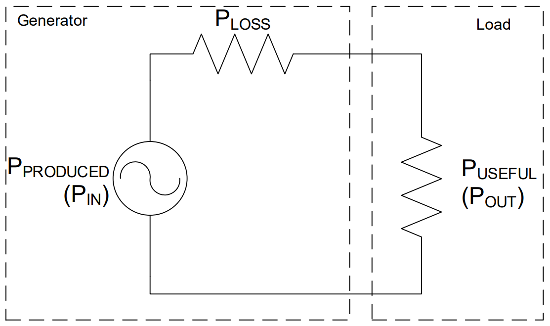
Fig. 5. Modeling losses in a system with a series resistor.
Example Problem 1
An AC-powered rotating beacon, modeled as a 120 kΩ resistor, is to be installed on an aircraft. Since the beacon requires 40 \(V_{RMS}\) to operate, a resistor is placed in series to act as a voltage divider. The aircraft generator produces a voltage of \(v(t) = 84.85\cos(360°\cdot400\cdot t)\ \text{V}\). If the required efficiency for this circuit is 85%, is this a viable option?
Fig. 17. Circuit for Example Problem 1: aircraft generator source in series with a voltage-dropping resistor R and a 120 kΩ beacon load.
Understand: This is a voltage division problem where the resistor R will drop voltage so the beacon only receives 40 \(V_{RMS}\). In the circuit, the power consumed by the beacon is useful. The power consumed by the resistor R, however, is wasted. We can model this scenario as the circuit to the right.
Identify Key Information:
Knowns: \(v(t) = 84.85\cos(360°\cdot400\cdot t)\ \text{V}\); the beacon needs 40 \(V_{RMS}\); required efficiency is 85%.
Unknowns: The current in the circuit, the resistance of the “loss resistor”, the voltage dropped across the “loss resistor”.
Assumptions: None.
Plan: Convert the source voltage to RMS. Use KVL to find the voltage drop across R. Use Ohm’s Law at the beacon to find the current. Then calculate efficiency.
Solve: Convert the source voltage to RMS (zero bias):
The source provides 60 \(V_{RMS}\) and the beacon drops 40 \(V_{RMS}\), so by KVL, R must drop 20 \(V_{RMS}\).
Fig. 18. Solved circuit for Example Problem 1: source at 60 V_RMS, R drops 20 V_RMS, beacon receives the required 40 V_RMS.
Using Ohm’s Law at the beacon to find the circuit current:
Power produced by the source:
Power consumed by the beacon:
Efficiency:
Answer: No, this is not a viable option since the efficiency is only 66.67%, which is less than the required 85%.
Motor Efficiency#
Now let’s look at how conservation of power applies within a DC motor. Figure 6 shows the relationship between the input electrical power we supply to the motor compared to the output power. The input power will be the voltage we provide across the terminal of the motor, \(V_T\), times the current going into the motor.
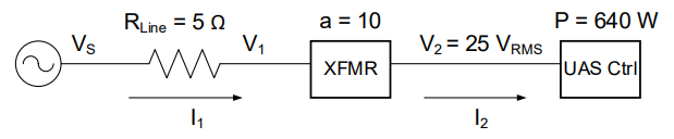
Fig. 6. Relationship between input and output power.
Before the electricity gets to the coils on the rotor to create the electromagnet, it must pass across the brushes/commutator. As those connections are made and switched, there is typically a little sparking. This is energy that is lost to heat/light, and we will call this \(P_{brush}\). Within the motor there are resistive (heat) losses due to the current flowing through components that have resistance, such as the copper wires in the coils. These are called copper losses or I²R losses. There are core losses within the electromagnet, such as the magnetic flux leaking outside the motor and molecules within the electromagnet consuming energy. These are lumped as core losses. Also, some power is lost to friction of the rotor spinning as well as air resistance. These mechanical losses are lumped together as \(P_{mech}\). All that is left is the power transferred out of the motor as torque.
If we model this discussion as a circuit with lossy devices, we would get the circuit below, where each loss mechanism claims a share of the input power before any useful work reaches the output shaft:
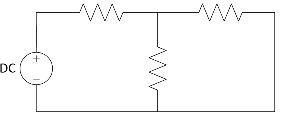
Fig. 7. A circuit modeling the losses in a motor.
Symbol |
Description |
|---|---|
\(P_{brush}\) |
Loss due to sparking during commutation |
\(P_{I^2R}\) |
Loss due to resistance of copper wires |
\(P_{core}\) |
Loss due to magnetic flux leaking outside the motor |
\(P_{mech}\) |
Loss due to friction |
We can use the input and output power to determine the efficiency of the motor. The efficiency tells us the percent of the input power that can be used at the output.
Notice that reducing any one of the four loss terms — for example, by using better bearings to cut friction losses — directly increases the numerator and improves efficiency, which is why motor design is heavily focused on minimizing each loss type.
Example Problem 2
An 87% efficient, 40-hp motor is plugged into a standard electrical outlet. How much power will it consume and how much current will it draw when operating at rated conditions?
Understand: By definition, a motor of a given rated horsepower is expected to deliver that quantity of power in mechanical form at the motor shaft. Since the motor is not 100% efficient, we will need to supply more power to the motor in order to account for the losses.
Identify Key Information:
Knowns: η = 87%, rating = 40 hp, outlet voltage = 120 \(V_{RMS}\).
Unknowns: Power consumed (\(P_{in}\)) and current drawn (\(I_{RMS}\)).
Assumptions: None.
Plan: Convert the horsepower rating to Watts. Use the efficiency equation to find \(P_{in}\). Then use the power equation to find \(I_{RMS}\).
Solve: Convert power from hp to W:
Use the efficiency equation to find the motor’s power requirement:
Since the outlet delivers 120 \(V_{RMS}\), use the average power equation:
Answer: The motor will consume 34.29 kW and draw 286 \(A_{RMS}\) when running at rated conditions.
Generators#
Thus far, we’ve exclusively discussed motors and have not really mentioned generators. However, generators, except in some very specialized cases, look exactly like motors, as illustrated in Figure 8. Physically, they are the same. Instead of applying a voltage and watching the rotor spin, we can physically spin the rotor to extract electrical energy. When the coils of wire on the rotor spin through the magnetic field of the stator, a voltage is induced in the coils of wire!
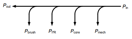
Fig. 8. Generator power flow.
In an aircraft, an AC generator is driven by the rotation of the engine, and Figure 9 shows the myriad of different generators and motors found on a standard aircraft. These generators are typically used to provide 115 \(V_{RMS}\) running at 400 Hz to the devices on board with some of it converted to DC voltage (we’ll talk about how to do that later in this block).
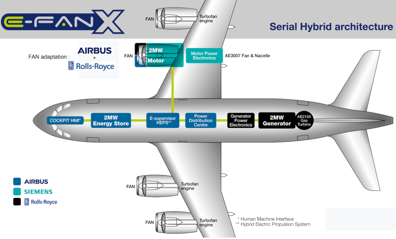
Fig. 9. An example of the power architecture of a commercial aircraft.
Power Generation#
Although electricity is all around us, very few of us give much thought to where it comes from. The power plants are usually, but not always, far removed from the population so we simply do not have to deal with them on a regular basis.
This was not always true though. In the late 1800’s, when electricity was first beginning to be used, multiple power stations were spread out through population centers due to the power losses (in the form of heat) caused by resistance in the wires travelling over long distances. The advent of transformers helped solve that problem, although it was a fierce battle between Thomas Edison and George Westinghouse/Nikola Tesla. The next lesson is devoted to explaining how transformers enable efficient transmission of power.
There are many advantages to having power plants far removed from population centers. This allows them to:
Be closer to the fuel/resources which generate the electricity
Be large plants which are more efficient due to economy of scale
Minimize the impact of exhaust/pollution within the community
As you would expect, power needs vary throughout the day, and those needs are classified into three categories: base power, intermediate power, and peak power. Base power is the minimum required power to meet the needs of an area. Intermediate power is a predictable increase in power demand throughout the day due to normal activities, such as lights and kitchen appliances being turned on in the evenings when people return home from work. Peak power is the absolute maximum power needed to fill unforeseen requirements, such as an especially hot or cold day (which means more air conditioners or furnaces are operating).
Almost all electrical power plants share one thing in common: electricity is generated by turning the shaft of a generator. The most common type of power plant is a thermal power plant. In these types of plants, water is heated to steam, which then passes through a turbine connected to the shaft of the generator. As the steam passes through the turbine, it causes the turbine and shaft to rotate, producing electrical energy. This process is seen in Figure 10.
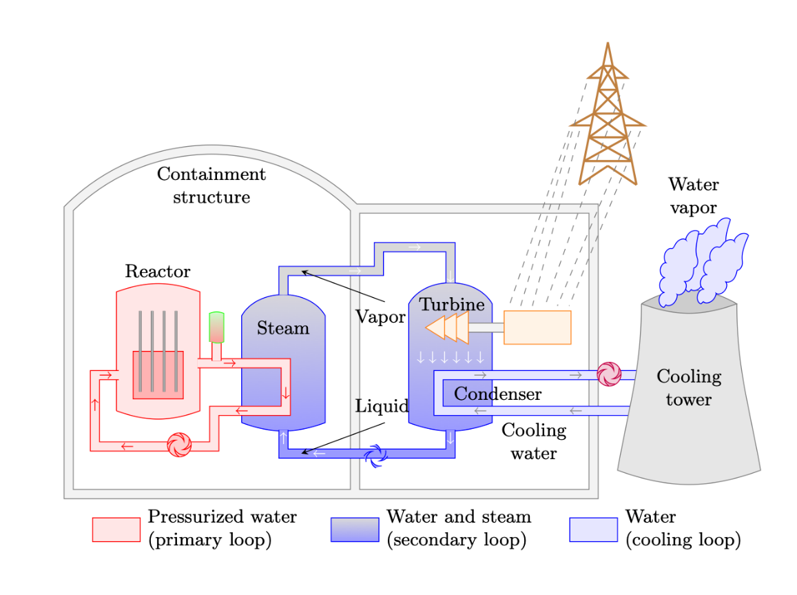
Fig. 10. A nuclear power plant is an example of a thermal power plant.
Steam is not the only way the shaft can be turned. Wind, water, expanded air, or mechanical energy from a motor can turn the shaft, generating electricity. However, more than 70% of our electricity is generated using steam to turn large turbines.
Electricity can be generated by several different sources, but the following six sources provide about 96% of our electricity.
Natural Gas. Natural gas plants use the expansion of the gas when it is burned to turn turbines (though some hybrid plants exist which also use steam) and provide approximately 40% of US electricity. Since they do not need to heat water for steam, they are very responsive to changing power needs and are often used to provide intermediate and peak power. While they are not as clean as nuclear plants, they have fewer emissions than coal plants. Their most severe disadvantage comes from the difficulty and high cost of transporting and storing natural gas in bulk due to its low density and instability (it’s prone to erupting into flames).
Nuclear. These thermal plants provide approximately 20% of US electricity and are also used for base loads since they cannot change their output quickly. Their primary advantages are that they provide a consistent amount of power and tend to be very cost effective. Similar to coal plants, they are poor candidates for filling intermediate and peak power requirements because they require more than a day to start up. In contrast to coal plants, nuclear plants do not emit contaminants into the atmosphere. However, the large amount of water required for cooling can have an environmental impact. Nuclear plants are a very popular electricity source in Europe, where France receives 80% of its electricity from nuclear production. On the other hand, construction of nuclear plants in the U.S. has stalled due to concerns about radiation accidents, such as the one from Three Mile Island in 1979. Furthermore, finding a long-term, safe method of disposing of waste products, especially for the enriched uranium used to make nuclear weapons, has been a significant problem.
Coal. These thermal plants are used for base loads since they cannot change their output quickly. Coal power plants provide 19% of U.S. electricity. Their primary advantages are that they provide a consistent amount of power and tend to be very cost effective, especially here in the U.S. where coal is relatively plentiful. They are poor candidates for filling intermediate and peak power requirements because they require more than a day to start up. They are also a source of pollution, which can damage the environment. The Clean Air Act of 1970 eliminated a significant amount of pollution caused by coal power plants, and now they are required to install equipment to limit contaminants.
Wind. Generating power by using wind to turn a turbine accounts for approximately 8% (and rising) of US electricity. Wind turbines tend to be cost effective because of their use of a renewable resource and are also “clean” (though many detractors point to their destruction of landscapes and impact on bird populations as environmental concerns). Because power generation is highly variable and completely unrelated to power needs, they are not reliable for meeting base or peak power needs. Additionally, in order for them to be useful in helping with intermediate loads, storage mechanisms are needed to keep the energy for periods when it is needed. For example, some wind turbine farms can redirect power to move water uphill into tanks where it can be released when required to generate hydroelectric power.
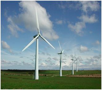
Fig. 11. Wind turbines.
Hydroelectric. Dams in the U.S. provide 7% of the country’s electricity by using moving water to turn a turbine. Once built, hydroelectric plants are relatively cost effective (so long as water continues to flow) and do not emit contaminants. They are very responsive to peak and intermediate power needs because of their ability to ramp up power generation by increasing water flow through the plant. These advantages make hydroelectric plants extremely popular; however, there are a limited number of locations where they can be built. Since we have no control over the location of a hydroelectric dam, they can be far from population centers, requiring significant infrastructure in order to transmit the power.
Solar. Solar power provides less than 2% of US electricity. There are two types of solar energy: thermal and photovoltaic. Thermal, like other thermal plants, uses the sun’s energy to heat oil which is then used to boil water. Photovoltaic, however, directly uses photons from the sun to excite materials like silicon to release electrons, directly creating electricity. Since clouds and storms can greatly reduce the power generated by solar power, it cannot be used for base or intermediate power loads. Even though solar power can be variable, it is used to help meet peak demand needs because peak demand tends to occur when the sun is at its strongest: during the day and in the summer. The benefits of solar are that it is a renewable resource and that it has a low operational cost. However, even though efforts are being made to reduce the costs associated with solar power, solar panels are expensive and require a large initial investment. Also, there are negative environmental impacts associated with manufacturing solar panels. Lastly, in contrast to wind farms where the land may be used for cattle grazing, it is difficult to repurpose the land once a solar farm has been built on it.
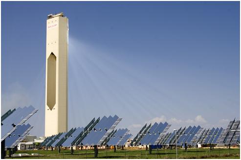
Fig. 12. A photovoltaic solar energy farm.
So far, we have focused on how electrical power is generated and how motors and generators convert energy from one form to another. Generating power, however, is only part of the problem. That power must also be delivered from power plants, often located far from where the electricity is used, to homes, businesses, and equipment. In the next section, we will examine how electrical power is transmitted over long distances and introduce transformers, which make efficient power transmission possible.
Power Transmission#
Towards the end of the 19th century, the first electric companies were developing power transmission systems. At the heart of this difficult engineering problem were losses due to line resistance over long distances. For example, a typical power line has a loss of 250 mΩ/km. When distances are small, we can ignore the relatively small resistance. However, looking at the US national and regional power grid layout in Figure 13, we see that power transmission distances are not usually small.
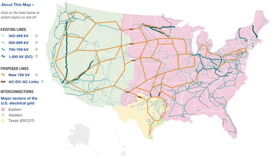
Fig. 13. US national power grid.
In most cases, the distance between substations and power generation sites (dam, coal plant, nuclear plant, etc.) is over 20 km, resulting in a line resistance of at least 5 Ω. Consider the efficiency of this scenario, as in Figure 14, where we have a power plant producing DC power then transmitting it across a large distance to a house, which consumes 12 kW at 120 V.
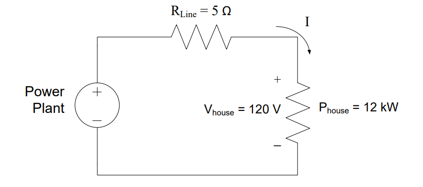
Fig. 14. Model of DC power transmission system.
Since we already know how much power is consumed by the house (12 kW), we need to figure out how much power is lost in the 5 Ω transmission line. The power plant, transmission line, and house are all in series, so they share the same current. Solving the power equation for the current through the house:
Since this is a series circuit, 100 A flows through each device. The power lost in the transmission line:
Therefore, for every 12 kW of power that is used, 50 kW is wasted!
In order to provide 12 kW to the house and cover the loss in the transmission line, the power plant needs to produce:
Which allows us to calculate the efficiency as:
Clearly, this is abysmal, and low efficiencies such as these would increase electricity costs drastically. Fortunately, our power transmission system uses AC power instead of DC power, which allows for much higher efficiencies. The main benefit of AC power is that it allows the use of transformers. Transformers allow the current to be reduced in the transmission line. Reducing the current is a great strategy as the current is typically the largest contributor to power losses.
Transformers#
Ampere’s Law states that an electric current running through a coil of wire will induce a magnetic field. Similarly, Faraday’s Law tells us that a time-varying magnetic field induces a voltage in a wire. So, even though a steady current induces a steady magnetic field, a steady magnetic field does not induce any voltage. To take advantage of the relationship between Ampere’s law and Faraday’s law, a time-varying current can be used to induce a changing magnetic field that in turn induces a voltage. In fact, transformers rely on this so-called mutual inductance. They are composed of two coils of wires (which are basically inductors) wrapped around a common core, along with insulation to isolate the two circuits.
The physical configuration of a transformer is shown on the left side of Figure 15. The coil of wire on the left side is known as the primary side, while the right side is known as the secondary side. The voltage drop on the primary side is typically denoted by \(V_p\) or \(V_1\), while the secondary side’s voltage drop is denoted by \(V_s\) or \(V_2\). Finally, note the ratio \(N_1\):\(N_2\), which is the turns ratio of the transformer. \(N_1\) is the number of turns in the primary, and \(N_2\) the number of turns in the secondary.

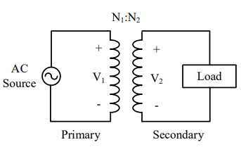
Fig. 15. The physical configuration of a transformer and a transformer shown in a circuit diagram.
In a transformer, the voltage per turn will be equal on both sides. Since each winding is a series arrangement of turns, more turns on the primary leads to a smaller voltage per turn. This happens because the same voltage drop has to occur across more turns. On the secondary, each turn increases the output voltage. This leads us to two interesting points. First, more turns on the primary leads to a smaller voltage drop on the secondary. Second, more turns on the secondary leads to a higher voltage drop on the secondary.
The efficiency of transformers is high by default, and by assuming an ideal transformer, power is conserved across the transformer’s primary and secondary sides. This means whatever power enters the primary must exit the secondary — the transformer redistributes voltage and current, but cannot create or destroy energy:
Notice the trade-off: stepping voltage up always steps current down by the same factor, and vice versa — you cannot get more voltage and more current simultaneously.
Since the ratio of \(V_1\) to \(V_2\) is equal to the turns ratio, we can also use the turns ratio to describe the relationship of the primary and secondary currents:
Transformer Turns Ratio
If \(N_2 < N_1\), then \(V_2 < V_1\) → step-down transformer (\(a > 1\))
If \(N_2 > N_1\), then \(V_2 > V_1\) → step-up transformer (\(a < 1\))
Sometimes, when we draw transformers, it is more convenient to draw block diagrams:
Fig. 16. Block diagram of a transformer with a voltage source and load.
In block diagrams, everything is assumed to be in series, unless the input or output of a device has multiple connections. In the example above, the source is providing power through the line, which is then connected to the transformer, with a turns ratio of a. The transformer then transforms the voltage and current and provides power directly to the load. This is a compact, concise way to draw electrical systems, and we will use it frequently as we talk more about how systems behave, rather than how individual circuits behave.
Example Problem 3
A transformer with 100 turns on the primary and 50 turns on the secondary is used to deliver power from a 120 \(V_{RMS}\) source to a 100-Ω load. How much power does the resistor consume? How much power does the source provide?
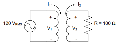
Fig. 19. Circuit for Example Problem 3: 120 V_RMS source connected to the primary of a 100:50 turns transformer with a 100 Ω load on the secondary.
Understand: We have two circuits here that interact through a transformer. On the left, the voltage source provides power to the primary side of the transformer. At the right, the secondary side of the transformer is effectively a new voltage source that drives the resistor.
Identify Key Information:
Knowns: \(V_{source}\) = 120 \(V_{RMS}\), \(N_1\) = 100 turns, \(N_2\) = 50 turns, R = 100 Ω.
Unknowns: \(P_{Source}\) and \(P_{Resistor}\).
Assumptions: The transformer is an ideal transformer with no power loss.
Plan: Use KVL to find \(V_1\), then use the turns ratio to find \(V_2\). Use Ohm’s Law to find \(I_2\), then the turns ratio to find \(I_1\). Finally, use the power equation on each side.
Solve: By KVL, \(V_1\) = 120 \(V_{RMS}\). Find the turns ratio:
Find \(V_2\) (step-down, since a > 1):
By KVL on the secondary side, \(V_R\) = 60 \(V_{RMS}\). Using Ohm’s Law:
Using the turns ratio to find \(I_1\):
Compute average power using RMS values:
Answer: The source provides 36 W, and the resistor consumes 36 W of average power. (This correlates with our intuition, as there is no modeled loss in the circuit.)
Example Problem 4
An AC Power Plant is 10 km away from a transformer with a turns ratio of 10 and a house that is using 12 kW of power. The 20 km of electrical wire to and from the transformer has a resistance of 5 Ω (roughly equivalent to a single 20 mm diameter aluminum wire), and the home runs on 120 \(V_{RMS}\). What is the efficiency of the system?
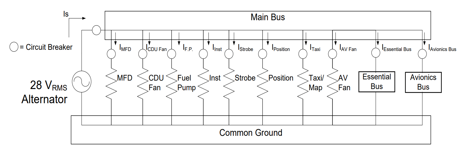
Fig. 20. Block diagram for Example Problem 4: AC power plant → 5 Ω transmission line → transformer (a = 10) → house consuming 12 kW at 120 V_RMS.
Understand: This system contains a transmission line from the source to the primary side of the transformer with some loss (modeled as a 5 Ω resistor).
Identify Key Information:
Knowns: \(P_{House}\) = 12 kW, \(V_{House}\) = 120 \(V_{RMS}\), a = 10, \(R_{Line}\) = 5 Ω.
Unknowns: Power produced by the power plant, efficiency η.
Assumptions: The transformer is an ideal transformer with no power loss.
Plan: Use \(P_{House}\) and \(V_{House}\) to find \(I_2\). Use the turns ratio to find \(I_1\) = \(I_{Line}\). Find \(P_{Line}\), then \(P_{PowerPlant}\) = \(P_{House}\) + \(P_{Line}\). Calculate η.
Solve: Current at the house:
Using the turns ratio to find \(I_1\) = \(I_{Line}\):
Power lost in the transmission line:
Total power produced at the plant:
Efficiency:
Answer: The efficiency of this power transmission system is 96%. By using AC power and a transformer, the efficiency of this system increased from 19.35% (DC, no transformer) to 96%!
Block Diagrams#
For the rest of this lesson, and much of the rest of the class, we will represent circuits as block diagrams. The “XFMR” block will represent a transformer. In later lessons, a block is labeled with the name of the component it is representing.
Example Problem 5
You are managing a team tasked to create the power supply system for a UAS controller station. The equipment consumes 640 W at a voltage of 25 \(V_{RMS}\). The transmission line is modeled as a 5 Ω resistor. Contractors have submitted Options A and B. Option A uses a transformer with a turns ratio of 10:1, while Option B uses a turns ratio of 25:1. Calculate the efficiency and required generator voltage for both options.
Fig. 21. Block diagram for Example Problem 5: generator → 5 Ω transmission line → transformer (turns ratio a) → 640 W UAS controller equipment at 25 V_RMS.
Understand: Here we have a block diagram of a power transmission system. The transmission line from the source to the transformer contains loss, modeled as a 5 Ω resistor.
Identify Key Information:
Knowns: \(P_{load}\) = 640 W, \(V_2\) = 25 \(V_{RMS}\), \(R_{Line}\) = 5 Ω. Option A: a = 10, Option B: a = 25.
Unknowns: Efficiency (η) and source voltage (\(V_S\)) for both options.
Assumptions: The transformer is an ideal transformer with no power loss.
Plan: Find \(I_2\) from \(P_{load}\) and \(V_2\). Use the turns ratio to find \(I_1\). Calculate \(P_{Line}\) and η. Use the turns ratio to find \(V_1\), then KVL to find \(V_S\).
Solve — Option A (a = 10):
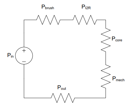
Fig. 22. Example Problem 5 Option A results (a = 10): 95.13% efficiency, generator voltage 262.8 V_RMS.
Solve — Option B (a = 25):
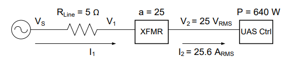
Fig. 23. Example Problem 5 Option B results (a = 25): 99.19% efficiency, generator voltage 630.1 V_RMS.
Answer: Option A (turns ratio 10:1) requires a 262.8 \(V_{RMS}\) generator and has 95.13% efficiency. Option B (turns ratio 25:1) requires a 630.1 \(V_{RMS}\) generator and has 99.19% efficiency.
Key Takeaways#
Motors and Generators. Motors convert electrical energy into rotational mechanical energy using electromagnetic attraction; generators reverse this process, converting mechanical rotation into electrical energy — the same physical machine can do both.
Motor Losses. Real motors lose power through brush/commutator sparking, copper (I²R) resistive heating, core magnetic losses, and mechanical friction; these losses reduce efficiency below 100%.
Efficiency (η). Efficiency is the ratio of useful output power to total input power (\(\eta = P_{out}/P_{in}\)) and is used to determine how much power a source must supply to deliver the required output.
Power Generation Sources. The US grid draws electricity primarily from natural gas (~40%), nuclear (~20%), coal (~19%), wind (~8%), and hydroelectric (~7%); each source has different startup speed, reliability, and environmental trade-offs.
Transformer Operation. A transformer uses mutual inductance between primary and secondary coils to step AC voltage up or down; the turns ratio a = N₁/N₂ = V₁/V₂ = I₂/I₁ governs the voltage and current relationships.
Step-Up vs. Step-Down Transformers. A turns ratio greater than 1 (N₁ > N₂) steps voltage down and current up; a turns ratio less than 1 (N₁ < N₂) steps voltage up and current down.
Transmission Efficiency. Stepping voltage up (and current down) before transmission dramatically reduces I²R losses in the line, improving system efficiency from as low as ~19% (DC, no transformer) to over 96% with a properly chosen AC transformer.