Practice Problems (KEY)
Problem 1

\[P_{in} = \frac{P_{out}}{\eta} = \frac{550\,\text{W}}{0.88} = 625\,\text{W}\]
\[I_{S,\text{RMS}} = \frac{P_{in}}{V_{S,\text{RMS}}} = \frac{625\,\text{W}}{120\,\text{V}_{\text{RMS}}} = 5.2\,\text{A}_{\text{RMS}} > 5.0\,\text{A (CB rating)}\]
The motor draws 5.2 A, which exceeds the 5 A breaker rating — the breaker trips.
Problem 2
\[P_{\text{load}} = 1.2\,\text{kW} + 1.8\,\text{kW} + 0.8\,\text{kW} + 5.2\,\text{kW} = 9\,\text{kW}\]
Must upgrade to the 12 kW generator — the 7 kW version cannot support the 9 kW total load.
Problem 3
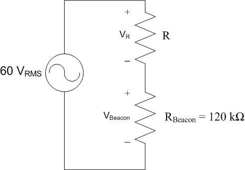
\[V_{S,\text{RMS}} = \frac{84.85\,\text{V}}{\sqrt{2}} = 60\,\text{V}_{\text{RMS}}\]
\[V_R = V_S - V_{\text{Beacon}} = 60 - 55 = 5\,\text{V}_{\text{RMS}}\]
\[I_S = \frac{V_{\text{Beacon}}}{R_{\text{Beacon}}} = \frac{55\,\text{V}_{\text{RMS}}}{120\,\text{k}\Omega} = 458\,\mu\text{A}_{\text{RMS}}\]
\[\eta = \frac{P_{\text{useful}}}{P_{\text{useful}} + P_{\text{wasted}}} \cdot 100 = \frac{V_{\text{Beacon}} I_S}{V_{\text{Beacon}} I_S + V_R I_S} \cdot 100 = \frac{55}{55 + 5} \cdot 100 = 91.7\%\]
Yes, this is a viable option because 91.7% > 85%.
Problem 4

\[R_{\text{eq}} = \left(\frac{1}{20\,\Omega} + \frac{1}{10\,\Omega} + \frac{1}{7\,\Omega + 8\,\Omega}\right)^{-1} = 4.62\,\Omega\]
\[P_{\text{load}} = \frac{V_{\text{gen}}^2}{R_{\text{eq}}} = \frac{(115\,\text{V}_{\text{RMS}})^2}{4.62\,\Omega} = 2.86\,\text{kW} = P_{\text{out,gen}}\]
\[\eta = \frac{P_{\text{out,gen}}}{P_{\text{in,gen}}} \cdot 100 = \frac{2.86\,\text{kW}}{3\,\text{kW}} \cdot 100 = \boxed{95.3\%}\]
Problem 5

\[P_{\text{out}} = 2\,\text{hp} \times \frac{745.7\,\text{W}}{1\,\text{hp}} = 1491.4\,\text{W}\]
\[P_{\text{in}} = \frac{P_{\text{out}}}{\eta} = \frac{1491.4\,\text{W}}{0.9} = \boxed{1.66\,\text{kW}}\]
\[I_{S,\text{RMS}} = \frac{P_{\text{in}}}{V_{S,\text{RMS}}} = \frac{1.66\,\text{kW}}{120\,\text{V}_{\text{RMS}}} = \boxed{13.8\,\text{A}_{\text{RMS}}}\]
Problem 6
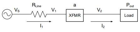
(a)
(b)
\[I_2 = \frac{P_{\text{House}}}{V_{\text{house}}} = \frac{1500\,\text{W}}{120\,\text{V}_{\text{RMS}}} = 12.5\,\text{A}_{\text{RMS}}\]
\[I_1 = \frac{I_2}{a} = \frac{12.5\,\text{A}}{10} = 1.25\,\text{A}_{\text{RMS}}\]
\[P_{\text{line}} = I_1^2 R_{\text{line}} = (1.25\,\text{A}_{\text{RMS}})^2(5\,\Omega) = 7.8125\,\text{W}\]
\[P_{\text{gen}} = P_{\text{house}} + P_{\text{line}} = 1500 + 7.8125 = \boxed{1507.8\,\text{W}}\]
\[\eta = \frac{1500}{1500 + 7.8125} \cdot 100 = \boxed{99.48\%}\]
\[V_{\text{gen}} = \frac{P_{\text{gen}}}{I_1} = \frac{1507.8\,\text{W}}{1.25\,\text{A}_{\text{RMS}}} = \boxed{1.206\,\text{kV}_{\text{RMS}}}\]
Problem 7
b. False — Transformers require AC power to operate. DC sources cannot be used with transformers.
Problem 8
Power lost in a transmission line is \(P_{\text{line}} = I^2 R\), so keeping current low minimizes losses. Transformers allow power to be transmitted at very high voltage (low current) and then stepped back down to usable levels. Since transformers only work with AC, the efficiency advantages of transformers drove the adoption of AC for the national grid.
Problem 9

(a) \(a = \frac{N_1}{N_2} = \frac{5}{1} = 5\) → step-down transformer
(b) \(V_S\) is in parallel with the primary coil, so \(V_1 = V_S = \boxed{200\,\text{V}_{\text{RMS}}}\)
(c) \(V_2 = \frac{V_1}{a} = \frac{200\,\text{V}_{\text{RMS}}}{5} = \boxed{40\,\text{V}_{\text{RMS}}}\)
(d)
\[R_{\text{eq,secondary}} = 4000\,\Omega + \left(\frac{1}{20000\,\Omega} + \frac{1}{5000\,\Omega}\right)^{-1} = 8\,\text{k}\Omega\]
\[I_2 = \frac{V_2}{R_{\text{eq,secondary}}} = \frac{40\,\text{V}_{\text{RMS}}}{8\,\text{k}\Omega} = \boxed{5\,\text{mA}_{\text{RMS}}}\]
(e) \(P_S = P_{\text{Load}} = V_2 I_2 = (40\,\text{V}_{\text{RMS}})(5\,\text{mA}_{\text{RMS}}) = \boxed{200\,\text{mW}}\)
Problem 10
\[a = \frac{V_1}{V_2} = \frac{120\,\text{V}_{\text{RMS}}}{30\,\text{V}_{\text{RMS}}} = \boxed{4}\]
Problem 11

(a)
\[I_2 = \frac{P_{\text{community}}}{V_2} = \frac{123\,\text{kW}}{120\,\text{V}_{\text{RMS}}} = 1.025\,\text{kA}_{\text{RMS}}\]
\[I_1 = \frac{I_2}{a} = \frac{1.025\,\text{kA}}{70} = 14.6\,\text{A}_{\text{RMS}}\]
\[P_{\text{line}} = I_1^2 R_{\text{line}} = (14.6\,\text{A}_{\text{RMS}})^2(10\,\Omega) = 2.14\,\text{kW}\]
\[\eta = \frac{123}{2.14 + 123} \cdot 100 = \boxed{98.3\%}\]
(b)
\[V_S = \frac{P_S}{I_1} = \frac{123\,\text{kW} + 2.14\,\text{kW}}{14.6\,\text{A}_{\text{RMS}}} = \boxed{8.57\,\text{kV}_{\text{RMS}}}\]
(c)
\[P_{\text{line}} = (14.6\,\text{A}_{\text{RMS}})^2(5\,\Omega) = 1.066\,\text{kW}\]
\[\eta = \frac{123}{1.066 + 123} \cdot 100 = \boxed{99.1\%}\]
Problem 12

\[I_2 = \frac{P_{\text{MOB}}}{V_2} = \frac{150\,\text{kW}}{120\,\text{V}_{\text{RMS}}} = 1.25\,\text{kA}_{\text{RMS}}\]
\[I_1 = \frac{I_2}{a} = \frac{1.25\,\text{kA}}{8} = 156.25\,\text{A}_{\text{RMS}}\]
\[P_{\text{line}} = (156.25\,\text{A}_{\text{RMS}})^2(2\,\Omega) = 48.8\,\text{kW}\]
\[\eta = \frac{150}{48.8 + 150} \cdot 100 = \boxed{75.4\%}\]
\[V_S = \frac{150\,\text{kW} + 48.8\,\text{kW}}{156.25\,\text{A}_{\text{RMS}}} = \boxed{1.27\,\text{kV}_{\text{RMS}}}\]
Problem 13

\[I_{2,\text{xfmr2}} = \frac{P_{\text{AFB}}}{V_{2,\text{xfmr2}}} = \frac{2.5\,\text{MW}}{120\,\text{V}_{\text{RMS}}} = 20.83\,\text{kA}_{\text{RMS}}\]
\[I_{1,\text{xfmr2}} = \frac{I_{2,\text{xfmr2}}}{a_{\text{xfmr2}}} = \frac{20.83\,\text{kA}}{500} = 41.67\,\text{A}_{\text{RMS}} = I_{\text{line}}\]
\[P_{\text{line}} = (41.67\,\text{A}_{\text{RMS}})^2(5\,\Omega) = 8.68\,\text{kW}\]
\[I_{1,\text{xfmr1}} = \frac{I_{2,\text{xfmr1}}}{a_{\text{xfmr1}}} = \frac{41.67\,\text{A}}{0.0625} = 666.7\,\text{A}_{\text{RMS}}\]
\[\eta = \frac{2.5\,\text{MW}}{8.68\,\text{kW} + 2.5\,\text{MW}} \cdot 100 = \boxed{99.7\%}\]
\[V_S = \frac{2.5\,\text{MW} + 8.68\,\text{kW}}{666.7\,\text{A}_{\text{RMS}}} = \boxed{3.76\,\text{kV}_{\text{RMS}}}\]