Practice Problems (KEY)#
Answer the following questions about the two modulated signals shown below.
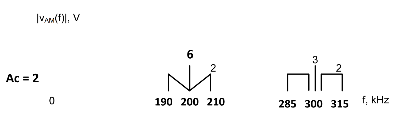
a. Find \(\alpha\).
Centered at 200 kHz signal:
Centered at 300 kHz signal:
b. Is this over-, under-, or 100%-modulated?
Centered at 200 kHz signal: under-modulated
Centered at 300 kHz signal: over-modulated
c. What kind of detectors can you use?
Centered at 200 kHz signal: envelope detector or synchronous detector
Centered at 300 kHz signal: synchronous detector
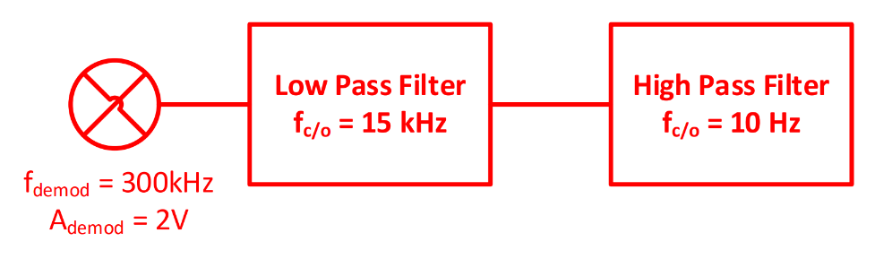
d. Design a demodulator for each signal and explain why you chose that demodulator.
Centered at 200 kHz signal: envelope detector — cheaper and easier to build
Centered at 300 kHz signal: synchronous detector — must use for any over-modulated signal
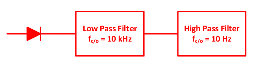
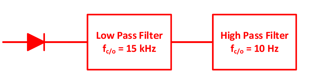
The output signal of an AM modulator is shown below in both the time and frequency domains. Since the signal is 100%-modulated, design an envelope detector to demodulate the signal.
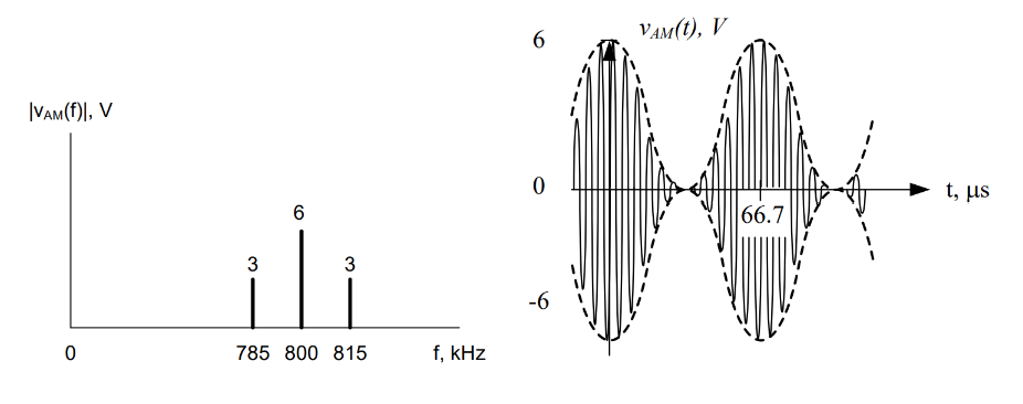
Since we are told the AM signal is 100%-modulated, we can use an envelope detector. The frequency components of the filters need to be determined. First, the low-pass filter must maintain all the frequency components in the original signal. From the spectrum, we can see that the sidebands are 15 kHz above and below the carrier frequency of 800 kHz. Therefore, the original message sinusoid was 15 kHz. We could also have determined this using the period of the time-domain plot. The inverse of 66.7 microseconds is 15 kHz.
We can then determine that an LPF with a cutoff frequency of 15 kHz or greater would suffice. For the high-pass filter, we know there is a bias component. Therefore, we need to filter out the bias. As long as we do not filter any of the message frequency components, we have a choice of cutoff frequencies, basically anything above 0 Hz, but normally less than 1 kHz. We choose 10 Hz.
Given the following AM signals on the frequency spectrum:
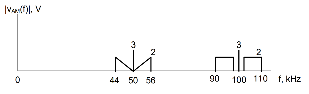
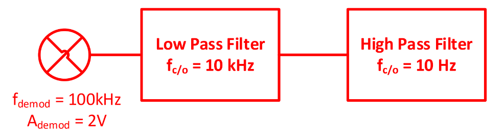
Design a synchronous detector to recover the message signal centered at 100 kHz.
Given the following AM signal, answer the questions below. Assume \(A_c = 1\ \text{V}\).
a. What is the modulation index, \(\alpha\), of this signal?
b. What is the power efficiency, \(\eta\), of this signal?
c. Identify one pro and one con of increasing the modulation index to \(\alpha = 3\).
Pro: higher power efficiency. If we have a higher modulation index, \(\alpha\), our power efficiency, \(\eta\), will also rise. This means a larger percentage of our transmitted power will be used to send the signal rather than the carrier frequency component, so less power is wasted.
Con: must use a more expensive, more complex demodulator (synchronous detector). When \(\alpha > 1\), the signal is over-modulated, and we cannot use the cheap, simple envelope detector. As a result, we must use a synchronous detector, which uses a function multiplier to demodulate the signal.
What is the purpose of the diode in an envelope detector?
a. Kill the bias
b. Kill the negative voltages
c. Kill the carrier
The diode works as a one-way street. Current can only flow in one direction. Therefore, when the polarity of the voltage switches and the current tries to flow in the other direction, the diode does not allow this to happen.
What is the purpose of the high-pass filter in a synchronous detector?
a. Kill the bias
b. Kill the negative voltages
c. Kill the carrier
The bias was added by the summer in the modulation process; therefore, it must be removed. The frequency of a bias is 0 Hz since a DC value never changes. Thus, an HPF with a cutoff frequency of 10 Hz would be sufficient.