Lesson 31 – Communications and Antennas#
Learning Outcomes
Identify the four types of communication media and their advantages and disadvantages.
Identify the four types of wireless radio frequency (RF) propagation methods and their advantages and disadvantages.
Calculate the relationship between frequency and wavelength for an electromagnetic wave.
Identify the different regions of the electromagnetic spectrum and which are typically used for communications.
Identify the usable range of the RF spectrum and the types of communications associated with them.
Calculate the maximum line-of-sight (LOS) distance between two objects given the height above the terrain for each.
Explain how a basic dipole antenna works.
Calculate the wavelength of an electromagnetic signal given the carrier frequency.
Explain what antenna gain is and the concept of an antenna gain pattern.
Identify the three basic types of antennas and their sizes, maximum gains, and basic gain patterns.
Communications#
Introduction#
Today, communication affects our lives in so many different ways. Given the ubiquity of smart phones and other connected devices, we can communicate with anyone at any given time. In the civilian world, we can request an Uber, buy tickets to a Denver Broncos game, or have near-instantaneous communication with someone across the country. In military operations, communication is even more important, as it provides critical information across the battlefield in near-real time. Delivering information using electromagnetic signals from one location to another requires some form of pathway or medium. These pathways can be broadly categorized as either wired (such as a transmission line) or wireless. We call these pathways communication media. Some people refer to them as communications channels, so you may hear these two terms used synonymously. In this lesson, we will first talk about four different communication media, to include wireless, and then discuss four types of wireless radio frequency (RF) propagation methods.
Before discussing communication media, we need to define some common terminology. Every sinusoidal signal has a wavelength, or the distance between two successive crests or troughs in the wave. In communications systems, this distance is typically measured in meters. Wavelength and frequency relate to each other using the following equation:
Where:
λ (lambda) is the wavelength of the signal propagated
c is the speed of light (3.0 x 10^8^ \(\frac{m}{s}\))
f is the frequency of the signal being propagated.
The relationship above shows that the wavelength of a signal gets larger as the frequency gets smaller. Understanding this relationship is critical as we go forward through this block, as communication media and antennas depend on the frequency of the signal being transmitted.
Communication Media#
In general, there are four main types of communication media:
Transmission Lines (wires)
Waveguides
Optical fibers
Wireless
|
|
Transmission lines (coaxial cable) |
Waveguide |
|
|
Optical Fibers |
Wireless |

Transmission Lines#
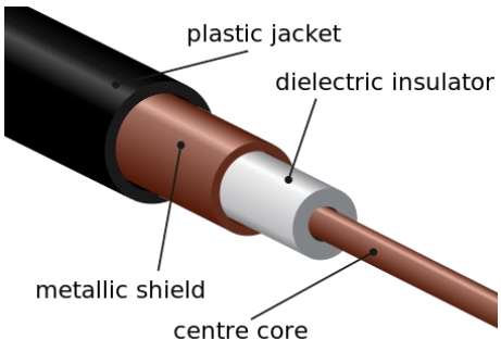
The principles governing transmission line behavior of were covered in Block 1. Recall, over long distances, transmission lines had an intrinsic impedance that reduced the efficiency of power transmission. Additionally, transmission lines can only support a limited range of frequencies. Specially designed lines (e.g., coaxial or Ethernet cables) can transmit signals up to a few hundred MHz, but above those frequencies wired transmission lines act like low pass filters.
Despite these drawbacks, transmission lines do have some advantages: 1) they are very reliable, 2) they are easy to repair, and 3) they are relatively secure.
Waveguides#
A waveguide is simply a hollow pipe through which an electromagnetic signal is sent. The internal surfaces of a waveguide are highly reflective allowing for very efficient transmission of the signal. Many waveguides are rectangular in shape, although some are circular. Some microwave ovens use waveguides to convey the energy from the magnetron, which creates the signal, to the cooking chamber. In satellite dishes, waveguides are used to connect the transmitter to the antenna.
The internal dimensions and shape of the waveguide determine which frequencies can be transmitted through it. If the wavelength is too large, the signal will not propagate in the waveguide. For example, high frequency signals have short wavelengths, so they propagate well through a waveguide; however, lower frequencies are blocked because of their long wavelengths. As such, a waveguide acts as a high pass filter. The cutoff frequency of a waveguide can be found using the equation:
In this equation, c is the speed of light and a is the length of the longest side of the waveguide as shown here:
Fig. 9. Rectangular waveguide cross-section: the longest internal dimension ‘a’ determines the cutoff frequency \(f_{c/o} = c / 2a\).
The primary advantage of waveguides is very low attenuation, which is to say the signal does not lose much power as it moves through the waveguide. Disadvantages of waveguides include being heavy, rigid, fairly difficult to repair, and expensive.
Example Problem 1
A freeway underpass is 8 m tall and 18 m wide. If the underpass acts as a waveguide, will a signal from an AM radio station be able to pass through?
Understand: Next time you’re driving, tune to an AM station before driving under an underpass and see what happens.
Identify Key Information:
Knowns: We know the dimensions of the underpass.
Unknowns: The cutoff frequency of the “waveguide”, which is the freeway.
Assumptions: AM radio stations transmit near 1 MHz. Additionally, we assume the underpass acts like a waveguide.
Plan: Since the freeway underpass acts like a high pass filter, we can use the waveguide equation to find the cutoff frequency and then compare that frequency with the frequency of an AM radio station.
Solve: The waveguide equation is:
Since the cutoff frequency of the underpass “waveguide” is above that of the typical AM radio station, the underpass should prevent any frequencies below 8.33 MHz from passing. Therefore, AM stations will be blocked. FM stations, on the other hand, transmit near 100 MHz, and the FM signals can be received under the same underpass.
Optical Fibers#
Optical fibers act like waveguides for beams of light, which are very high frequency signals. The light signal itself is most often a laser beam, modulated by the information that is being sent. When transmitting light in an optical fiber, the light beam bounces off the sides of the glass fiber as it travels at the speed of light. Optical fibers allow for very large bandwidths, and even allow multiple signals (different “colors” of light) to be transmitted on the same fiber. Additionally, the fibers are flexible and are relatively inexpensive (especially when considering cost per bandwidth). Finally, optical fibers have relatively low loss per unit distance.
The primary disadvantage of optical fibers is that they are very difficult to install and repair. Fibers must be entirely replaced, or spliced using complex equipment. Splicing optical fibers results in the introduction of additional loss into the fiber. For example, the F-22 uses optical fiber to implement its “fly-by-light” system, but maintaining the cabling can be a nightmare for the crews, especially when donned in CBRNE gear.
Wireless#
Wireless communications use the electromagnetic spectrum to transmit and receive information without the use of wires, waveguides, or other conductors. Typically, a wireless signal is transmitted from an antenna, then it travels through free space until it is acquired by the receiving antenna. This is exactly what happens every time you use your cell phone. Even though radio frequencies and antennas are commonly associated with wireless communications, laser beams can also be used to communicate. A great example of this is the Lunar Laser Communications Demonstration (LLCD) developed by MIT Lincoln Laboratory. The LLCD used lasers to successfully transmit at a data rate of 622 Mbps from lunar orbit to Earth!
The primary advantages of using wireless communications are flexibility and cost. Wireless communications can be used virtually anywhere, as long as the transmitter and receiver have the required equipment. There is no need to install or repair wires over long distances, so they are relatively cheap to use and maintain.
The primary disadvantages of wireless communications are that they have limited bandwidth and are not as reliable as the other communications media. As we discussed earlier in this class, the radio frequency spectrum in the United States is full, meaning there is no more bandwidth available at radio frequencies for wireless communications. Additionally, wireless communications are not as reliable as the other communications media. For example, satellite TV, which uses wireless communications, can lose service during severe storms whereas cable TV, a transmission line, does not. Despite these disadvantages, wireless communications are widely used in today’s world, and for that reason, various wireless communications will be the focus of the rest of this block.
Wireless Communications#
Imagine this scenario: you are stranded behind enemy lines, a few kilometers from the smoking remains of your airplane. From intelligence briefs received before the mission, you know you’re in a safe area, with only a very slight chance of capture. Still, you find a reasonably sheltered spot and pull out your survival radio, hoping to contact a rescue helicopter.
In order to communicate with the helicopter, you will need to communicate wirelessly. In your situation, though, how does it work? To be successful, you will need to understand how wireless communications work and what factors affect your communication system’s performance.
Radio Frequency (RF) Spectrum#
The lower end of the electromagnetic spectrum, called the RF spectrum, is subdivided into eight bands spanning from 3 kHz to 300 GHz. Each band has a name, as shown in Figure 1. Civilian applications, such as commercial AM and FM radio, television, cellular telephony, civilian aviation navigation, and air traffic control frequencies are found in this portion of the electromagnetic spectrum. These bands are also used in many military applications: global positioning system (GPS); RADAR; munitions guidance and fusing systems; strategic and tactical communications systems; and intelligence, surveillance, and reconnaissance (ISR) systems.
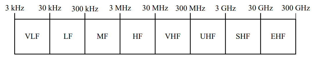
Fig. 1. The RF spectrum.
RF Propagation methods#
There are four different kinds of wireless RF propagation methods. They are:
Direct or line-of-sight (LOS)
Surface wave
Sky wave
Forward scatter
Each of these pathways involves a propagation path. Since it is possible for a signal to be transmitted over several paths simultaneously, this may cause interference. However, some of the pathways only work for certain bands within the RF spectrum.
Line-of-sight (LOS) Propagation: All electromagnetic energy (to include all the RF bands) will propagate by LOS. If you, the transmitter, are in view of the receiver, then line-of-sight is established, thus the name. In practice, this means that if nothing can obstruct the waves traveling directly between the transmitter and receiver, then line-of-sight propagation can occur. As shown in Figure 2, LOS communications on the earth are limited by the curvature of the earth and the heights of transmitting and receiving antennas. Of course, transmitter power is also a limiting factor. The signal transmitted from point T reaches the receiving antennas \(R_1\) and \(R_2\). However, \(R_3\) is not in the LOS path of the signal and cannot receive any of the radio’s energy. For communication and telemetry between earth and space vehicles, LOS propagation is used. At short distance, secure military communications commonly occur through LOS microwave links. Some telephone company “trunks” and cell phone towers also use LOS.
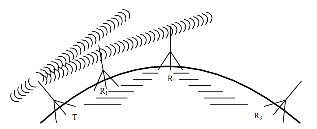
Fig. 2. Line-of-sight (LOS) propagation between several repeater stations.
Surface Wave Propagation: In surface wave propagation, the radio wave travels from the transmitting antenna to the receiving antenna along the surface of the earth. This wave essentially diffracts around the surface of the earth, so you can reach distances greater than LOS. In this waveguiding process, minute eddy currents are induced in the ground directly beneath the surface wave. Although the ground is a fairly good conductor, it does have some resistance and the energy required for these currents to flow is absorbed from the wave. This in turn limits how far the wave can effectively travel.
As frequency increases, losses due to the conductivity of the ground also increase and greatly attenuate the surface wave. This means surface waves cannot travel as far at higher frequencies. Surface waves are very effective for signal propagation in the VLF and LF bands. However, near the MF band, this effectiveness decreases rapidly. Surface waves are not generally useful above about 3 MHz. Commercial AM broadcasting stations typically use surface waves to transmit their signals - this is one of the main reasons AM radio signals can travel much further than FM radio signals.
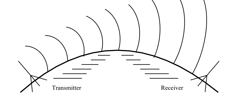
Fig. 3. Surface wave propagation.
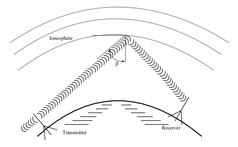
Sky Wave Propagation: Radio energy reflected or refracted from the ionosphere back to Earth is known as a sky wave. To understand how the ionosphere affects radio waves of different frequencies, think of the ionosphere as a huge mesh sieve surrounding the earth. Whether or not a wave passes through this sieve depends partially upon the relative dimensions of the wavelength and of the mesh openings. Therefore, radio energy with a long wavelength (low frequency) is more likely to be reflected back to Earth than that with a short wavelength (high frequency), which will pass through the mesh. In addition to frequency, the angle of incidence, β in Figure 4 below, plays a role in determine if the radio energy will be reflected back to Earth.
Fig. 4. Sky wave propagation.
In general, the larger the angle, β, the greater the probability the wave will be reflected. However, if β is too large, the layers of the ionosphere will act like a waveguide and the wave will effectively remain in the ionosphere and not be returned to Earth. As with the other wireless RF propagation methods, there is often a tradeoff between this angle of incidence and frequency. That is, for a given angle, there is some maximum frequency that can be used for sky wave propagation. Likewise, for a given frequency (within certain limits), there is some maximum angle that will produce a sky wave.
Maximum usable frequencies usually lie in the HF band; waves whose frequencies are above this are refracted slightly by the ionosphere but propagate through it. A peculiarity of the ionosphere is that its lower layers readily absorb energy in the MF band. Thus, sky waves in this band are possible only at night when the lower ionospheric layers are less dense. Narrowband long haul communications are often conducted in the HF band via sky wave.
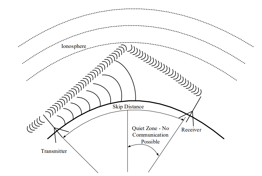
Sky wave propagation has a significant limitation. At the point where a sky wave returns to Earth, you can detect a very strong signal. However, between this point and the transmitter, there is essentially no energy from the sky wave at all. The distance between the transmitting antenna to the spot where the reflected wave strikes the earth is called the skip distance. At all locations less than the skip distance from the transmitting antenna, none of the sky wave signal is received. Therefore, the only way to communicate at points less than the skip distance is through LOS or surface wave communications.
In the HF band, where surface wave propagation is somewhat less than 200 miles, there is often a considerable distance in which essentially no radiated energy from either the surface wave or the sky wave is present and no communication is possible. This region is called the quiet zone. Figure 5 below illustrates the concepts of skip distance and quiet zone.
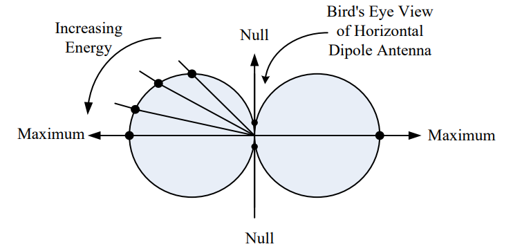
Fig. 5. Skip Distance and Quiet Zone.
Forward Scatter Propagation: When a radiated signal strikes the discontinuous “blobs” of air in the troposphere, it is scattered in various directions. Some of this scattering is in the forward direction, and the resulting radio signal, although relatively weak, can be received at a point that is beyond the horizon from the transmitter. Most of the Air Force’s non-satellite wideband long haul communications use forward scatter (with carriers in the 300 to 400 MHz range).
Although the scatter is dependent upon atmospheric conditions, it is possible to achieve reliable communications using high-power transmitters and sensitive receivers. Tropospheric forward scatter is effective in the VHF, UHF, and SHF bands. These tropo links use large rectangular “billboard” antennas and typically transmit about 100 kW of power. Before satellite communication became prevalent, much in-theater military communication was accomplished using this type of propagation.
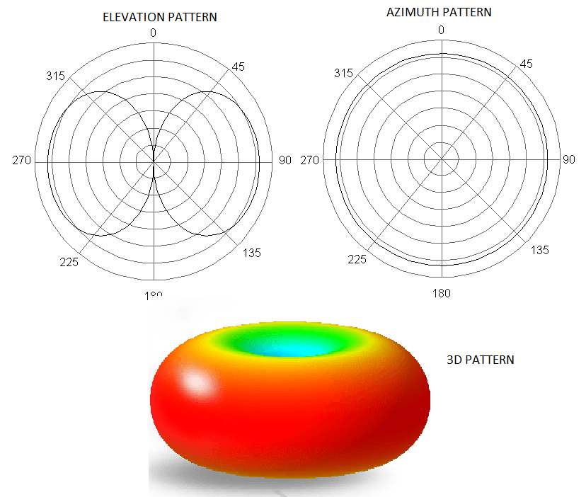
Fig. 6. Forward scatter propagation.
Range and Bandwidth Considerations#
At higher carrier frequencies, more bandwidth is available for use. As a rough estimate, the available bandwidth for a signal is about 1% of the carrier frequency.
AM radio stations, operating around 1 MHz, only have 10 kHz of bandwidth available. Fiber optics, however, use beams of light with carrier frequencies on the order of 100 THz (100 trillion cycles per second). These light beams have available bandwidths up to 1 THz. In other words, we can transmit approximately 100 Million times more information over a light beam than we can over a radio signal.
Unfortunately, the transmission range of signals also depends on the frequency. AM radio stations can easily transmit signals hundreds of miles, and as said earlier, these signals can even follow the curvature of the earth to reach beyond line of sight (surface waves). Light beams, on the other hand, are quickly attenuated by atmospheric effects. In order to overcome this limitation while still reaping the benefits of the huge bandwidth available in beams of light, optical fibers are generally used. We’ll discuss how frequency affects a signal’s range in more depth in future lessons.
RF Summary#
Let’s quickly summarize which types of wireless communication pathways are used by different radio frequency bands. This information is identified below in Figure 7. The ITU (International Telegraphic Union) designation of frequency bands (e.g., VHF, UHF) and the frequency ranges for some of the more common uses of radio waves are indicated. Since the transmitted signal in a communication system usually has a relatively narrow bandwidth, the propagation characteristics are determined almost exclusively by the carrier frequency. This figure also summarizes which radio frequencies are best suited to the four primary pathways that radio frequency waves propagate through the air and space: direct or line-of-sight (LOS), surface wave, sky wave, and forward scatter.
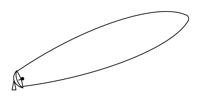
Fig. 7. The RF spectrum and the associated wireless RF propagation methods.
VLF and LF (Very Low Frequencies and Low Frequencies): At these lower frequencies, surface waves are attenuated very little and may be used for signal propagation of a thousand miles or more. This maximum distance gradually decreases with increasing frequency and is about 400 miles at 300 kHz. The sky wave does exhibit slight fluctuations with changes in the ionosphere, but it is still fairly reliable. Sky waves can be used for communication over distances from about 500 to 8000 miles in the LF band. In the VLF range, the combination of the surface and sky wave mechanisms make worldwide signal propagation possible with radiated power levels of about 1 MW.
MF (Medium Frequencies): In this band, the maximum distance for surface wave propagation varies from about 400 miles at 300 kHz to about 200 miles at 3MHz. Ionospheric absorption of electromagnetic energy in this band (maximum absorption occurs at 1.4 MHz) makes sky wave propagation impossible during the day. At night, sky waves furnish reception at distances from about 100 to 3000 miles.
HF (High Frequencies): The attenuation of surface waves above about 3 MHz is so great that the surface wave is effectively of no use for communication in this band. Sky waves are used extensively, and their behavior is mostly governed by ionospheric conditions. Although sky wave propagation is not always reliable, it is possible over distances of 12,000 miles and more. For distances such as this, frequencies from 5 to 20 MHz have proven most effective. Many military aircraft have HF radios onboard used for long-range communication. Also, amateur radio (ham radio) operates primarily in this part of the spectrum. Amateur radio is primarily used by hobbyists who are interested in RF communications.
VHF (Very High Frequencies): Although sky waves may occur at lower VHF frequencies, their reliability is so poor in the VHF band that they are virtually useless for communication. The predominant form of propagation in this band is line-of-sight. The effectiveness of forward scatter becomes increasingly important as frequencies reach 50 MHz and above.
UHF and SHF (Ultra High Frequency and Super High Frequency): Line-of-sight propagation is widely used at these frequencies since excellent low-noise reception is possible. Ranges of a few hundred miles can be realized up to about 10 GHz. Most forward scatter applications use frequencies well below this. Many space assets use this frequency band for communications.
EHF (Extremely High Frequency): Line-of-sight is the only propagation method used with EHF. Radio waves at these frequencies attenuate quickly in many uses, such as RADAR and wireless communications, so range is limited for these frequencies. Additionally, the atmosphere absorbs energy from waves, further attenuating them while in the atmosphere. However, EHF is still used. Each satellite in the Advanced Extremely High Frequency (AEHF) satellite constellation uses EHF for uplink communications. Additionally, 5G cellular networks will use frequencies in the lower portion of the EHF band. Specifically, Verizon has stated that they use 28 GHz (SHF) and 39 GHz (EHF) for their 5G network.
Line-of-sight Communications#
Returning to our original question, “What kind of wireless RF propagation method would you use between you and a rescue helicopter?” Realistically, you’ll most likely find yourself trying to establish a LOS link. A survival radio does not have the power required to use the more specialized forms of wireless communications (surface waves, sky waves, and forward scatter). In LOS, the key to establishing communications is actually being able to “see” the helicopter and having enough transmission power.
Obviously, there are a number of variables associated with determining the LOS between you and the helicopter. Are you on a hill or in a valley? How high is the hill? Is the terrain flat or bumpy? How high is the helicopter?
If we assume the terrain is relatively flat, we can use a simple equation to give us a good idea of how far the helicopter (or anything else) can see. Consider an antenna sitting at height, h, above sea level. The maximum range, r, between transmit and receive antennas is calculated as the distance from the transmit antenna to the point that is tangential to the surface of the earth as shown in Figure 8.
Fig. 8. Line-of-sight communication range.
Since \(R_{e}\) and r make two sides of a right triangle, with (\(R_{e}\) + h) as the hypotenuse, we can use the Pythagorean theorem (\(a^{2} + b^{2} = c^{2}\)) to find:
For terrestrial and even some airborne applications (i.e., non-space), we can assume that \(R_{e}\) is much greater than the antenna height (\(R_{e} \gg h)\), so the \(h^{2}\) can safely be ignored. This results in a maximum LOS range equation of:
Furthermore, the radius of the Earth is adjusted to account for atmospheric effects (decreasing atmospheric pressure helps bend radio waves downward thus increasing range). The resultant radius is increased from 3960 miles to 5280 miles, using the common 4/3 radius model. Coincidentally, there are 5280 feet in a mile. As a result, we can employ a “mixed units” equation, entering the antenna height (h) in feet to find the range in miles. This makes our LOS equation:
Line-of-Sight Range
In this equation, h is the height (in feet) of the observer, and r is the distance (in miles) the observer can see before the horizon gets in the way. Notice this is an “improper” equation, which is to say the units don’t match - if we take the square root of feet, we should not end up with miles. As engineers, we’re willing to overlook this discrepancy and use this improper equation because it is useful, and its derivation produces a mathematically logical result.
Example Problem 2
A helicopter is searching for a downed airman from 2000 feet AGL (above ground level). Assuming relatively flat terrain, how close will it have to get to the airman before it can establish line-of-sight?
Understand: Military survival radios require line-of-sight to communicate, so we need to calculate the maximum LOS distance.
Identify Key Information:
Knowns: We know the height of the CSAR helicopter.
Unknowns: The maximum line of sight distance.
Fig. 10. Example Problem 2 diagram: CSAR helicopter at height h above flat terrain, with LOS range r to the horizon.
Assumptions: We assume the terrain is flat (mountains cause significant problems).
Plan: We will use the LOS equation to solve for the maximum LOS distance.
Solve: We know the helicopter is 2000 feet above the earth. Plugging this into the LOS equation gives:
Recall, we put feet into the equation and the answer will be given in miles.
Answer: At 2000 feet AGL, the helicopter can see for approximately 63.25 miles. Therefore, it needs to be within 63.25 miles to see an airman on the ground.
Example Problem 3
The helicopter in the previous example is still flying at 2000 feet AGL. If the airman climbed to the top of a 50-foot tall hill, how far away could the helicopter establish line-of-sight?
Understand: We have to use the LOS equation twice because the airman has raised himself above the surface, as shown below.
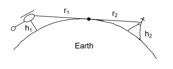
Fig. 11. Example Problem 3 diagram: helicopter and stranded airman on a hill — LOS range is the sum of ranges from each elevated point to the horizon.
Identify Key Information:
Knowns: We know the height of both the helicopter and the stranded airman.
Unknowns: The maximum LOS distance.
Assumptions: The terrain is flat and no mountains are in the way.
Plan: Recall, we are trying to determine the maximum distance the helicopter can see the airman. As the picture above hopefully shows, this occurs when the airman climbs high enough to just barely be in the helicopter’s line-of-sight. At this point, the helicopter will see the airman on the horizon, not even knowing the airman is standing on a hill (since the hill is below the helicopter’s horizon). From the point of view of the airman, the helicopter will also appear right at the horizon. Calculating this maximum LOS distance is very straightforward. We first figure out how far the horizon is from the helicopter, and then, we figure out how far the horizon is from the airman. If we add these two distances, we get the maximum distance they can see each other.
Solve: We already calculated the distance from the helicopter to the horizon in the previous problem. It is 63.25 miles. Since the airman is on a 50-foot hill, the distance for him to the horizon is:
Adding these distances together gives us our answer:
Answer: The airman and the helicopter now have a maximum LOS distance of 73.25 miles, which is 10 miles farther than before.
Antennas#
Introduction#
Generically, we can divide electronic communications into four steps:
Preparing the message for transmission using an input transducer, signal conditioning, and modulator
Sending the signal through a communications medium
Receiving the signal from the communications medium
Recovering the message using a receiver interface, demodulator, and transducer
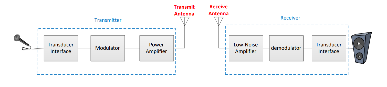
Fig. 12. Complete communications system block diagram: transducer → signal conditioning → modulator → transmit antenna → propagation → receive antenna → demodulator → output transducer.
In previous lessons, we learned about steps 1 and 4. We prepare the message by converting the information to an electrical signal, conditioning the signal, filtering, and/or digitizing, then modulating the signal for transmission. Likewise, we recover the message by demodulating and employing optional signal conditioning techniques, such as converting to analog, amplifying, and/or filtering, before we send it to an output transducer.
In the remaining lessons, we will focus on wireless communications. As we do so, we will use radio communications and RADAR as examples. We will then explore how this process affects our tactics by taking a look at Electronic Warfare (EW) techniques. But first, we will look at how we transmit a signal wirelessly with an antenna.
General Antenna Theory#
Coulomb’s Law states an electric force exists between a stationary positive charge and a stationary negative charge. Since the electric field is just the force per unit of charge, the electric field pattern in the following figure can be found by knowing the direction of force on a positive test charge placed in the vicinity of the two fixed charges. The arrows indicate the direction of force on a positive test charge, if one existed. Since positive test charges follow the direction of electric field lines and negative charges behave in the opposite manner as positive test charges, we know that negative charges must move in the direction opposite of the arrows on the electric field lines.
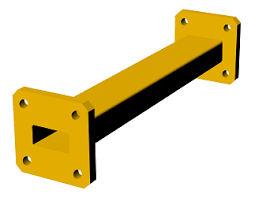
Fig. 13. Electric field lines around stationary positive and negative charges: field lines point from positive to negative, showing the direction of force on a positive test charge.
In this case, the charges are stationary. However, Ampere’s Law states that if the charges move along a conductor (such as a wire or a sheet of metal), these moving charges (current) generate a magnetic field around the current. The charge separation causes an electric field, and the current causes a magnetic field. Together, we call these interdependent fields an electromagnetic field, which radiates away from the conductor in waves, much like ripples from a stone thrown in a pond. But instead of the two-dimensional rings in the pond, the electromagnetic waves radiate outward in three-dimensional spheres. The radiation of electromagnetic waves can be explained well with a specific type of antenna called a dipole antenna, which will be discussed in more detail later in this reading. Consider a dipole antenna made out of two wires as shown in the figure below.
Fig. 14. Simple dipole antenna made from two wires: the antenna is an open structure that creates an electric field between the two halves when a voltage is applied.
Recall that oppositely charged particles attract and similarly charged particles repel one another. Recall also that metals easily give up electrons, which can create areas of positive charge (when electrons have departed) and negative charge (when electrons accumulate).
When we apply a voltage across the input of this antenna, we cause similarly charged particles to accumulate together:
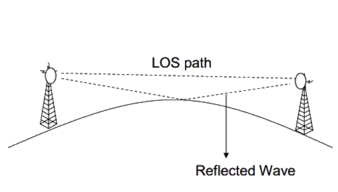
Fig. 15. Dipole antenna with voltage applied: negative charges accumulate at the bottom half, positive charges at the top half, creating a charge separation and electric field.
Therefore, in the bottom half of this antenna, the input, which is the negative terminal of \(V_{in}\), pushes the electrons in the lower wire away, causing an accumulation of negative charge at the bottom of the antenna. Similarly, in the top half of the antenna, there is a positive charge at the input, which draws electrons in the wire towards the input, leaving behind an area of positive charges at the tip of the antenna (we can denote positive charge as the absence of electrons). The result is an area of positive charges at one tip of the antenna and an area of negative charges at the other. The difference in charges between the two ends of the antenna creates an electric field, labeled E in the above diagram.
Now what happens if we were to put another antenna inside this electric field?
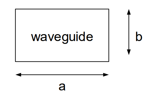
Fig. 16. Receiving antenna placed inside the transmitting antenna’s electric field: the E field forces charges in the receiving antenna to redistribute, inducing a voltage.
In the diagram above, the antenna we applied a voltage to is on the left, and the new antenna is on the right. As discussed earlier, the arrows on electric field lines tell us the direction of force on a positive test charge, and from this, we know that electrons will move in the opposite direction of the arrows. For this reason, the electric field, E, created by the antenna on the left moves electons to the top portion of each half of the antenna on the right, creating an area of negative charge at the top of the upper half and an area of positive charge at the bottom of the lower half. Another way to think about this is about how charges attract and repel. The arrows in an electric field originate from an area of positive charge, and they end in an area of negative charge. The positive charge at the top of the electric field draws electrons to the top of the new antenna. Likewise, the negative portion at the bottom of the electric field pushes the electrons away, leaving behind an area of positive charges in the new antenna.
In order for an electric field to propagate (move), the input needs to change over time. One way we can get it to change is by applying an alternating current, such as a sinusoidal signal, to the input.
Therefore, when the input signal reverses polarity, the electric field is reversed. We now have negative charges at the top of the transmitting antenna and positive charges at the bottom.
In the receiving antenna, the opposite occurs. Positive charges accumulate at the top of the receiving antenna and negative charges accumulate at the bottom.
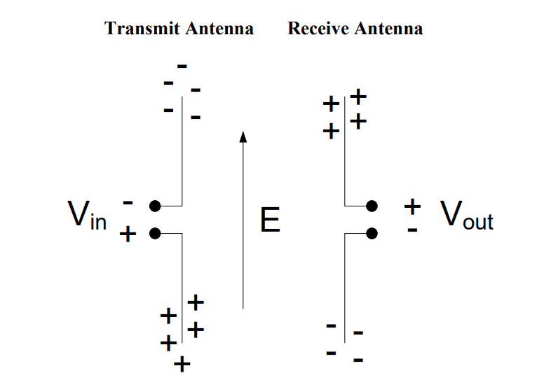
Fig. 17. Charge distribution in transmitting (left) and receiving (right) dipole antennas: opposite charge polarity in the receiver demonstrates how antennas transfer information.
Therefore, as our input signal from the transmitting antenna changes from positive to negative, the output signal at the receiving antenna changes from negative to positive. This is how antennas transmit information!
This also demonstrates an important concept about how antennas radiate electromagnetic radiation. The electric field travels perpendicular to the antenna, and the electric field points parallel to the antenna. In order for the electric field to move the charges in the receiving antenna, the receiving antenna has to be placed parallel to the incoming electric field (as is shown in the image above). For this reason, antennas do not work well when the tips are pointing at each other.
We could just as easily have made the antenna on the right the transmitting antenna (connected to \(V_{in}\)) and the antenna on the left the receiving antenna (connected to \(V_{out}\)). Because of this, there is no difference between a receive antenna and a transmit antenna. If an antenna can be used to transmit, it can also be used equally well to receive.
Types of Antennas#
There are many types of antennas, but we will discuss four main types: the dipole, monopole, parabolic dish, and array antenna.
Dipole: The basic dipole is one of the most common types of antennas. Its radiation characteristics, simplicity of deisgn, and ease of construction make it useful for a wide variety of applications. Although there are many types of dipoles, the most common type of antenna is the half wavelength dipole (also know as half-wave dipole), where the length of the antenna is given by:
Half-Wave Dipole Antenna Length
In the above equation, λ is the wavelength of the electromagnetic wave that the antenna is designed to transmit and/or receive. In calculating the length of antennas, it is useful to recall the relationship between wavelength (λ) and frequency:
Wavelength and Frequency
The following example illustrates how to calculate the length of a half-wave dipole.
Example Problem 1
The carrier frequency of an FM broadcast station is 100.7 MHz. How long of a dipole antenna should we use to receive this signal?
Understand: The length of the antenna is inversely proportional to the frequency of the signal.
Identify Key Information:
Knowns: We know the broadcast frequency (100.7 MHz).
Unknowns: The wavelength and the length of the dipole antenna.
Assumptions: None.
Plan: A dipole antenna is half of a wavelength, so we need to calculate the wavelength and then divide the wavelength by 2.
Solve: To find the wavelength of a signal, we use the following equation:
Therefore, this signal has a wavelength of just under 3 meters. A half-wave dipole antenna is one half of the wavelength of the signal. Therefore,
Answer: The dipole antenna needs to be 1.490 m (4.6 ft) long. Many cars embed a dipole antenna in the car window to receive FM signals. These antennas are roughly 1.5 meters in length (or just under 5 feet) to maximize reception of the frequencies used for FM stations.
Monopole: Another very common antenna is the quarter-wave monopole. As its name suggests, the length of a quarter-wave monopole is equal to one-quarter of the wavelength it is designed to transmit or receive. In order for a monopole antenna to work, it needs to have a reflective surface called a ground plane. This ground plane acts like a mirror to the electromagnetic field, which reflects the “mirror image” of the incident electromagnetic field. Then, the field from the top half and “mirror image” from the bottom half interfere constructively, meaning they add together. Using this phenomenon, the ground plane “fools” the quarter-wave monopole into behaving like a half-wave dipole.
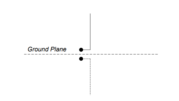
Fig. 18. Quarter-wave monopole antenna above a ground plane: the ground plane acts as a mirror, making the monopole behave like a half-wave dipole.
The radiation characteristics of the quarter-wave monopole are the same as that of the half-wave dipole from the ground plane up. Radio antennas mounted on cars are monopoles. This antenna works the same as if the sheet metal of the car under the antenna, functioning as the ground plane, were replaced by the bottom half of a half-wave dipole.
Example Problem 2
The carrier frequency of an FM broadcast station is 100.7 MHz. How long of a monopole antenna should we use to receive this signal.
Understand: We are recalculating the previous example problem using a monopole antenna to broadcast. However, since a monopole is half the length of a dipole, we know the monopole length will be shorter than the dipole.
Identify Key Information:
Knowns: We know the broadcast frequency (100.7 MHz).
Unknowns: The wavelength and the length of the monopole antenna.
Assumptions: None.
Plan: Since we calculated the wavelength of this signal in the problem above, we can start from there and divide by 4 to calculate a quarter of a wavelength. The antenna length is therefore:
Answer: The required length of a monopole antenna is 744.8 mm. The antennas that you see sticking out of car hoods are monopoles. 744.8 mm is about 2.5 feet, which is the approximate length of car antennas.
Example Problem 3
An AM radio station transmits at 740 kHz. If the station broadcasts using a monopole antenna, how tall should the antenna be?
Understanding: A monopole antenna needs to be 1/4 of the wavelength.
Identify Key Information:
Knowns: We know the broadcast frequency (740 kHz).
Unknowns: The wavelength and the length of the monopole antenna.
Assumptions: None.
Plan: We will use the same process as before, calculating the wavelength of the signal and then dividing it by 4.
Solve: Calculating the wavelength of this signal:
Recognize how large this wavelength is. In fact, the wavelength for this signal is more than 4 football fields long. Even with a quarter-wave dipole, the required antenna height is still:
Answer: A monopole antenna broadcasting a 740 kHz signal needs to be 101.4 m (332.7 ft) tall.
Remember a monopole antenna requires a ground plane in order to work. For an AM monopole antenna, the ground itself is used as the ground plane (sometimes metal bars are buried in the dirt to increase the reflectivity).
You might also wonder about the answer to the above question. If we need such a long transmission antenna, we need an equally long receiving antenna, which is impractical for many space-limited applications. Fortunately, there are some convenient ways to make antennas more usable. In fact, many AM antennas are not just one length of wire. Instead, a typical AM antenna is actually a thin copper wire wrapped around a frame hundreds of times. This wrapping allows us to create a necessarily long antenna while conserving space.
Parabolic Dish: A parabolic dish antenna (shown below) focuses signals in a specific direction, which allows them to travel farther. Recall that a parabola focuses parallel rays to its focal point. The actual antenna element, called the feed, is usually a dipole or horn antenna placed at the focal point. The feed acts as either a collector (receiver) or emitter (transmitter) for the antenna. In the receiving case, the feed collects all the rays focused by the parabolic reflector dish. In this way, the antenna can capture much more of the energy than just the feed antenna by itself. However, this is limited to a very small spatial area. In the transmitter case, the feed directs the energy towards the dish, where the energy is then focused in the direction the antenna is pointing. Note spherical and parabolic antennas are very similar but differ slightly in the way they focus energy.
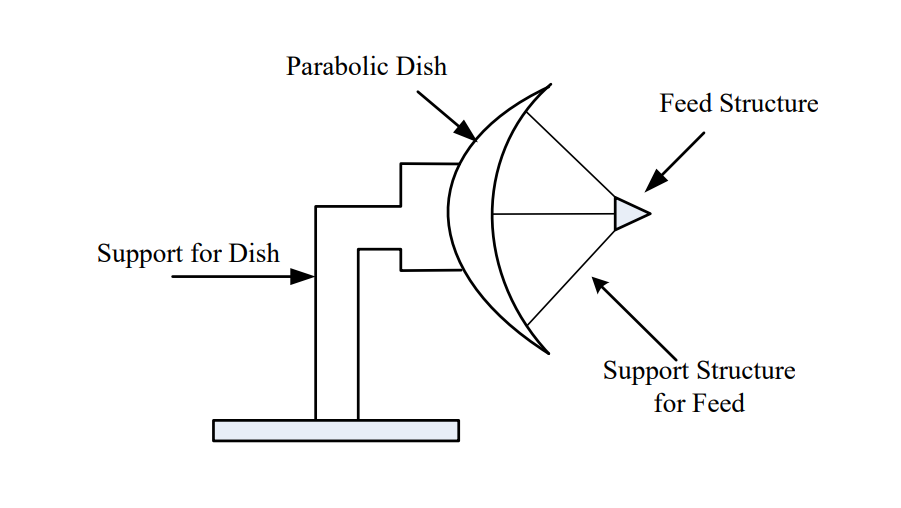
Fig. 19. Parabolic (dish) antenna: a feed antenna at the focal point directs energy toward the reflector dish, focusing the beam for high gain in one direction.
Antenna Parameters#
In what directions do antennas radiate energy and how much energy do they radiate in each direction? In what directions do antennas transmit or receive energy and how much energy do they transmit or receive in each direction? Thankfully, the concepts are the same whether the antenna is transmitting or receiving. In order to answer these questions, we graph the radiation patterns of an antenna. This provides a pictorial representation of the amount of energy the antenna radiates (or receives) in all directions for some arbitrarily chosen fixed distance. Consider once again the dipole antenna. If we want to know how much relative power is radiating in all directions from the antenna, we can create a radiation pattern graph.
Consider what would happen if we placed the dipole vertically and walked around the dipole in a circle, keeping our distance to the antenna constant. In this case, we would find all of the received power measurements are equal. So the radiation pattern around the axis parallel to the orientation of the dipole would be a circle as shown in Figure 1. For the radiation pattern, the outward distance from the center of the dipole represents power and not distance in meters. Therefore, if the radiation pattern is closer to the antenna, less power is being radiated in that direction.
Next, we can place the dipole antenna in a horizontal position walk around it in a circle while taking power measurements. The radiation pattern for this case is shown in Figure 2. We see the maximum power radiates from the two points on the circle farthest away from the side of the antenna. We also see no energy radiates off the end, where there is a null in the pattern. In addition, as we go from the null to the maximum on the circle, the energy gradually increases.
Figure 1: Vertical dipole radiation pattern |
Figure 2: Horizontal dipole radiation pattern |
|---|---|
|
|
Combining the radiation patterns shown above, the three-dimensional radiation pattern is shaped as a toroid, the shape of a doughnut, as shown in Figure 20. This radiation pattern explains why you never point the top of a radio antenna in the direction from which you are trying to receive signal. Instead hold the radio upright so the entire length of the antenna can capture radiation.
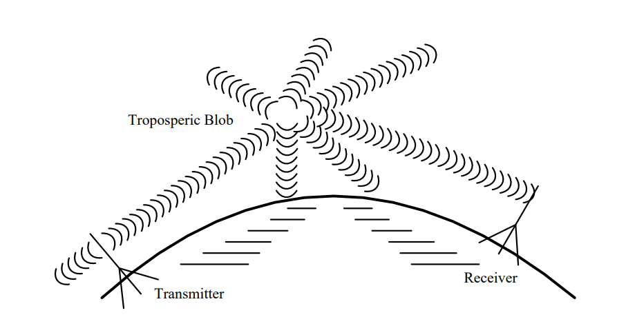
Fig. 20. 3-D radiation pattern for a simple dipole antenna.
A parabolic dish has a different radiation pattern because of its ability to focus radiation in one direction. The pattern is narrower and longer as shown below. This means a parabolic dish radiates and receives extremely well in a specific direction at the expense of poor performance in every other direction.

Fig. 21. Radiation pattern of a parabolic dish antenna: narrow main lobe in one direction, providing high gain with low response in all other directions.
Antenna gain refers to the antenna’s ability to focus energy in a specific direction. You might be familiar with flashlights that can focus the light beam by turning the head of the flashlight. As the beamwidth becomes narrower, the light intensity becomes brighter. The brightness of the bulb is constant; however, as the light from the bulb is focused, it can be concentrated into one direction. In antenna terminology, we would say the brighter, narrower beam has more gain.
Antenna gain is defined as the ratio of the energy focused in a direction as compared to a standard. The standard is a radiating point source, which is simply an antenna that radiates equally in all directions. This is called an isotropic source and is only a theoretical concept. The 3-D radiation pattern from a point source is simply a sphere, meaning it radiates energy equally in all directions. If the antenna does nothing to focus energy in a specific direction, its gain is simply one.
When we compare the radiation pattern of a dipole antenna (two circles in the figure below) to that of a point source (grey circle in the figure below), we find the dipole antenna has more power radiated in some directions than the point source (Gain > 1) while in some directions, no power is radiated (Gain = 0 or a null zone).
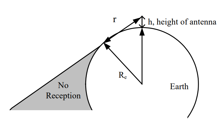
Fig. 22. Dipole antenna gain pattern (blue) overlaid on the isotropic point source pattern (grey circle): the dipole has more gain off the sides and a null off the ends.
Both the dipole and monopole have modest gain. Ideally, a half-wave dipole has a gain of G = 1.64. The quarter-wave monopole ideally has twice the gain of a half-wave dipole (G = 3.28). However, this is only true if the monopole is directly over a perfectly conductive ground plane that extends to infinity, which is rarely the case.
Since gain is typically a power ratio, it is usually discussed in terms of the ratio of the actual antenna power pattern gain compared to the power pattern gain of the point source. As stated above, this ratio is 1.64 for a half-wave dipole. We can also relate this in terms of decibels, or dB using the following relationship:
Remember, dB is a power ratio.
In contrast to a dipole or monopole, a parabolic dish antenna would typically have a gain ranging from hundreds to even thousands of times that of a point source and depends on both how the dish is built and the frequency of the transmitted signal. We can calculate the gain of a dish antenna using the following equation:
Parabolic Dish Antenna Gain
In this equation, r is the radius of the circular dish (in meters), λ is the wavelength of the transmitted signal (in meters), and η is the efficiency of the antenna.
Example Problem 4
A dish antenna with a radius of 250 mm is used to send a microwave communication signal at 2.7 GHz. The dish has an efficiency of 91%. What is the antenna’s gain?
Understand: A dish antenna has a high gain, but this gain depends on the relationship between the radius of the dish and wavelength of the transmitted or received signal.
Identify Key Information:
Knowns: We know the radius of the dish, the efficiency, and the frequency.
Unknowns: The wavelength and gain of the antenna.
Assumptions: None.
Plan: Since we have the dish’s radius and efficiency, we can calculate its gain for 2.7 GHz transmission using the gain equation. But first, we should calculate the wavelength.
Solve: The wavelength of the transmitted signal is
We can now calculate the gain:
Answer: The dish’s gain is 181.9.
Phased Array Antennas#
Now that we have discussed the three basic types of antennas and their associated parameters, it is worth looking at one more type of antenna – the phased array antenna. Although dish antennas focus their energy in one direction, one of their drawbacks is the need to physically turn the antenna in the direction of the corresponding transmitter or receiver. However, it is possible to construct an array of antennas to create an electronically controlled beam. Consider the arrangement of transmitting antenna elements shown in Figure 23, where 8 antenna elements are connected to a single transmitter/exciter. In this case, the direction of the combined beam appears to be moving at some angle θ off the “straight ahead” direction (boresight). To do this, each radiating element (antenna) is progressively delayed in phase (which is really just a time delay). For Figure 23, this delay increases as we move up the chain of antennas. Recall that as waves propagate, they spread out spherically. Therefore, by introducing this progressive delay, the peaks, or strongest parts of the waves, interfere constructively. The peaks of the overall wave from the array antenna define the direction the beam appears to be propagating. As such, the beam appears to be moving away from the array at the desired angle θ. Therefore, we can change the angle by changing the time delay between each element.
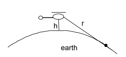
Fig. 23. A phased array of antenna elements.
Taking advantage of this abilty to change the direction of the “beam” by changing the time delay of the antenna elements allows us to build a completely flat antenna. Many modern antennas in aircraft, satellites, and other weapon systems use such phased array technology. One example is the Northrop Grumman AN/APG-83 Scalable Agile Beam Radar (SABR) used in the nosecone of the F-16 (Figure 24). Technology in the area of phased arrays has improved such that we can realize relatively high gain antennas and also steer the beams in both azimuth and elevation (2-D steering).
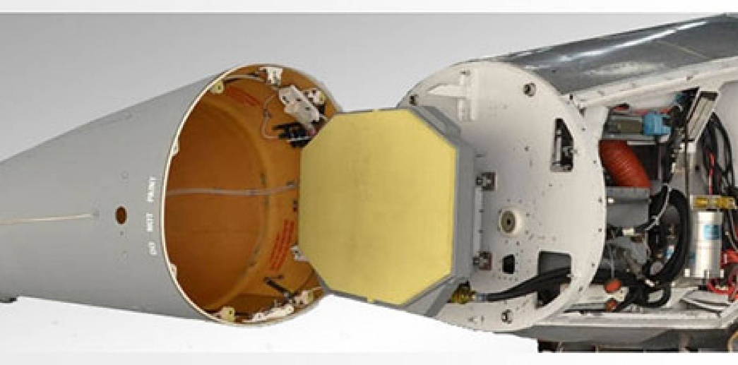
Fig. 24. The AN/APG-83 SABR installed in the nosecone of an F-16.
Key Takeaways#
Four RF propagation methods. Line-of-sight (LOS), surface wave, sky wave, and forward scatter each suit different frequency bands and distances; LOS is the most common for tactical military communications.
Line-of-sight range equation. The maximum LOS range between two elevated points is \(r_\text{total} = \sqrt{2h_1} + \sqrt{2h_2}\) (height in feet, range in miles), and both antenna heights directly extend the communication range.
Wavelength and frequency. Wavelength and frequency are inversely related by \(\lambda = c/f\); lower frequencies produce longer wavelengths, which affects antenna size, propagation behavior, and available bandwidth.
Dipole and monopole antenna lengths. A half-wave dipole must be \(\lambda/2\) long and a quarter-wave monopole must be \(\lambda/4\) long; both lengths scale with the wavelength of the signal being transmitted or received.
Antenna gain. Gain measures how effectively an antenna focuses energy in a particular direction compared to an isotropic point source; a parabolic dish achieves very high gain (hundreds to thousands) by focusing energy into a narrow beam.
Parabolic dish gain equation. Dish gain is \(G = (2\pi r)^2 \eta / \lambda^2\), so gain increases with dish radius and decreases with wavelength, meaning higher-frequency signals produce higher gain from the same physical dish.
Phased array antennas. By introducing progressive time delays across an array of antenna elements, phased arrays can electronically steer the beam direction without mechanically moving the antenna, enabling rapid and precise beam pointing.