Lesson 36 – Operational Risk Management in Integrated Air Defense Systems and Operational Cyber#
Learning Outcomes
By the end of this lesson, you should be able to:
Identify the major components of an Integrated Air Defense System (IADS).
Explain how an IADS kill chain works and identify ways to disrupt it.
Evaluate missions using Acceptable Level of Detection (ALD) and Acceptable Level of Risk (ALR).
Explain major differences between cyber warfare and traditional physical warfare.
Analyze common techniques used to gain unauthorized access to networks in military and operational environments.
Relate radar cross section (RCS) aspect dependence to survivability and mission planning.
Introduction#
In previous lessons, we focused on how individual RADAR systems detect and track targets. Individual radars are powerful, but they don’t tell the whole story.
In practice, modern air defense is rarely a single sensor operating alone. Instead, it is organized as a system of systems — a networked architecture in which detection, tracking, command and control (C2), communications, and weapons work together. This coordinated architecture is called an Integrated Air Defense System, or IADS.
A platform may evade one radar perfectly, only to be detected by a second sensor operating on a different frequency band, correlated by a C2 node, and passed to a weapons battery via a data link. Defeating one component of the system is not the same as defeating the system. This is the core challenge of survivability planning.
This lesson also introduces an operational decision framework built around two concepts:
Acceptable Level of Detection (ALD): How much detection can a mission tolerate?
Acceptable Level of Risk (ALR): How much loss or mission degradation can a commander tolerate?
Finally, because modern IADS architectures depend on digital networks, we connect this discussion to operational cyber — a domain with its own unique properties, vulnerabilities, and planning considerations.
What Is an Integrated Air Defense System (IADS)?#
An Integrated Air Defense System (IADS) is a coordinated, networked assembly of:
Detection sensors
Communication systems
Command and control (C2) nodes
Weapon systems
…designed to detect, identify, track, engage, and neutralize airborne threats.
The word integrated is the key. The components do not operate independently. Information is shared across the architecture so that multiple sensors and decision-makers contribute to the same common air picture. This makes the system substantially more effective than any single radar or missile battery operating in isolation.
Major IADS Components#
Component |
Function |
|---|---|
Early Warning / Search Radars |
Long-range detection of airborne objects |
Acquisition Radars |
Refined detection; prepares data for handoff to tracking |
Tracking Radars |
Refines position, velocity, and identity to engagement-quality accuracy |
Passive Sensors |
Non-emitting sensors (e.g., ESM receivers); detect targets without revealing their own position |
Communications Links |
Move data between sensors, C2 nodes, and weapons |
C2 Nodes |
Fuse data from multiple sources, assign engagement priorities, direct weapons |
Weapons Systems |
Surface-to-air missiles (SAM), anti-aircraft artillery (AAA), airborne interceptors |
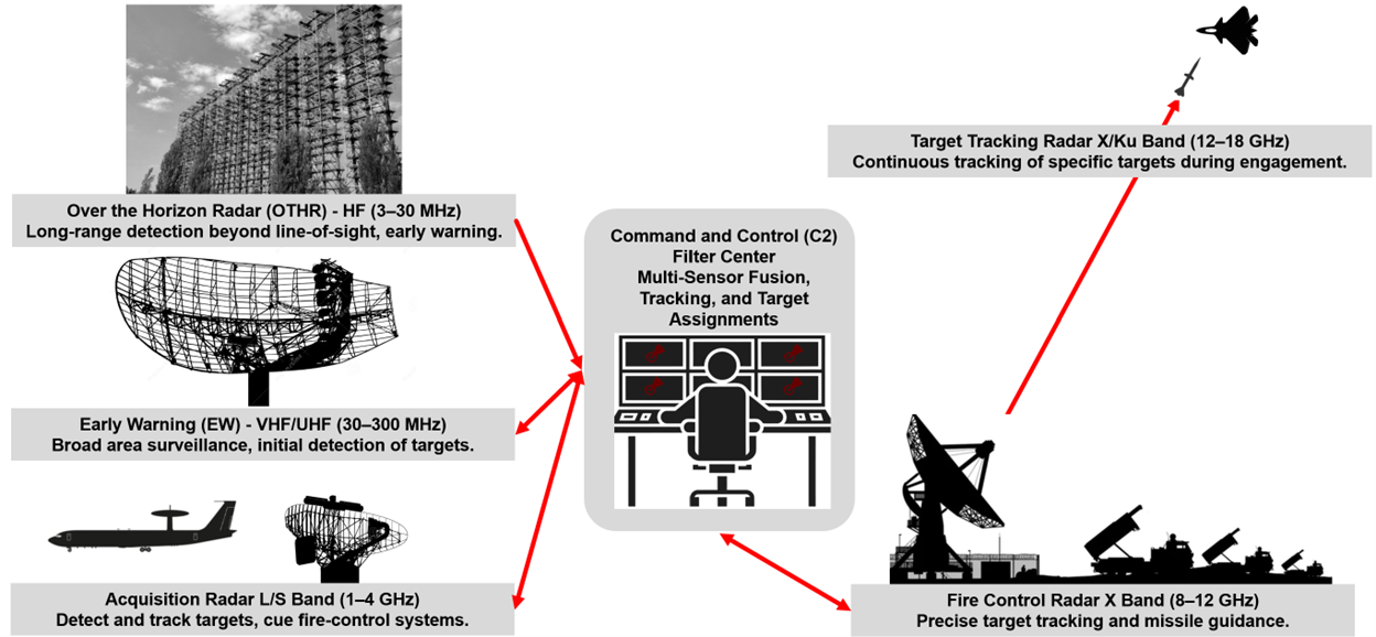
Fig. 1. IADS architecture: active sensors, passive sensors, and communications links feed C2 nodes that direct weapons systems against tracked targets.
Multi-Band Coverage as a Layered Defense#
A key design feature of a well-built IADS is the combination of radars operating across multiple frequency bands:
Band |
Frequency Range |
Typical Role |
|---|---|---|
HF |
3–30 MHz |
Over-the-horizon radar |
VHF |
30–300 MHz |
Long-range early warning; some LO-resistant capability |
UHF |
300 MHz–1 GHz |
Surveillance and acquisition |
L |
1–2 GHz |
Long-range surveillance |
S |
2–4 GHz |
Medium-range search and acquisition |
X |
8–12 GHz |
High-resolution tracking and fire control |
Ku |
12–18 GHz |
Precision tracking and missile guidance |
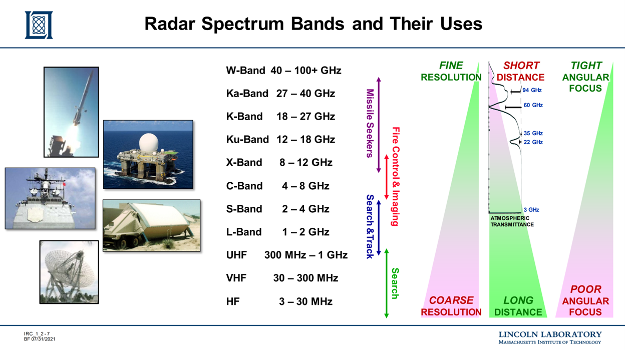
Fig. 2. Multi-band IADS radar coverage: HF through Ku-band radars provide layered detection from long-range early warning (VHF/UHF) to precision fire control (X/Ku).
Each frequency band trades off resolution, range, and sensitivity differently. Lower-frequency radars (VHF, UHF) have longer wavelengths and are more resistant to some shaping-based low-observability approaches. Higher-frequency radars (X, Ku) provide finer angular resolution for precise tracking and weapons guidance. By fielding radars across multiple bands, an IADS designer hedges against any single technique being used to defeat all sensors simultaneously.
Integration Advantages#
From an operational perspective, integration provides:
Better situational awareness
Faster decision-making loops
Improved engagement precision
Greater resilience against electronic warfare
Graceful degradation — if one node is attacked, others can compensate
That last point is critical. If an aircraft defeats one radar, the IADS may still function because another sensor or C2 path can keep the kill chain alive.
IADS Communication Architecture#
To understand how to defeat an IADS, you need to understand how it is connected. The communication architecture is typically a mix of technologies chosen based on required data rate, mobility, survivability, and node spacing.
Common Communication Methods#
Method |
Typical Use |
Key Strengths |
Key Vulnerabilities |
|---|---|---|---|
Fiber optic links |
Permanent installations, high-data-rate backbone |
High bandwidth; EM-intercept resistant |
Fixed; physically severable |
Commercial wireless |
Mobile or distributed sites |
Convenient; widely available |
Security and reliability concerns |
Tactical data links |
Missile guidance, AWACS coordination, sensor-to-shooter |
High capability; purpose-built |
Susceptible to jamming, spoofing, cyber exploitation |
The Network Is the Weapon System#
The IADS should be understood as a networked combat system, not merely a collection of radars and missiles. If the communication links fail, the integrated system fragments into isolated local sensors and shooters — a far less capable opponent.
The link architecture of an IADS is directly analogous to a distributed computing network. Nodes without connectivity lose their ability to participate in the shared air picture. Targeting the network layer — rather than individual sensors — can produce disproportionate effects.
The IADS Kill Chain#
The air defense kill chain is the sequential set of functions that must occur for a successful engagement. If any link in the chain is broken, the engagement fails.
The Eight Steps#
1. DETECT     ──►  2. IDENTIFY  ──►  3. TRACK
                                          │
8. ASSESS     ◄──  7. GUIDE     ◄──  4. CORRELATE/FUSE
                                          │
                   6. ASSIGN    ◄──  5. DECIDE
Step |
Description |
|---|---|
1. Detect |
A sensor detects a potential airborne object |
2. Identify / Classify |
Determine if the object is friend, foe, or neutral |
3. Track |
Refine position and velocity to build a usable track |
4. Correlate / Fuse |
Combine data from multiple sensors into a unified picture |
5. Decide |
C2 node determines whether to engage |
6. Assign |
Assign a specific weapon system to the target |
7. Guide |
Provide guidance data to the missile or interceptor |
8. Assess |
Evaluate whether the engagement succeeded |
Why Breaking the Chain Early Matters#
Break the Chain Early
Break the chain as early as possible, and for as long as possible.
Consider the contrast:
If you break the chain at Step 1 (Detection): Steps 2–8 never happen. The IADS never knows you exist.
If you break the chain at Step 7 (Guidance): The system has already detected, tracked, correlated, and assigned a weapon to you. You are surviving in an active engagement — a much more dangerous position.
Early disruption is almost always preferable.
Disrupting the IADS Kill Chain#
The goal is to disrupt the IADS early and continuously by creating layered effects across the architecture. Available tools include:
Low observability (LO) design
Flight path and altitude management
Electronic attack (jamming)
Communications denial
Cyber operations
Kinetic attack
Combinations of the above
Breaking the Chain at Early Warning and Search Radars#
Target: Steps 1–2 (Detect and Identify)
The best outcome is to prevent detection entirely. Techniques include:
Reduced radar cross section (RCS): Shaping and materials that reduce reflected power back to the radar
Flight path selection: Exploiting terrain masking, radar horizon geometry, and beam gaps
Altitude management: Staying below radar line-of-sight or in clutter-heavy regions
Emissions control (EMCON): Minimizing own-ship RF emissions
Jamming: Raising the noise floor or inserting false targets to prevent track formation
Breaking the Chain at Acquisition and Tracking Radars#
Target: Steps 3–4 (Track and Correlate)
Once a system moves from broad-area search to precise tracking, the goal is to prevent a usable three-dimensional track. Techniques include:
RCS shaping: Maintaining favorable aspect angles toward fire-control radars
Noise or deception jamming: Degrading range or angle measurement accuracy
Maneuver: Changing velocity vector to break track continuity
Cyber effects: Corrupting tracking or correlation software functions
Breaking the Chain at Filter Centers and C2 Nodes#
Target: Steps 4–6 (Correlate, Decide, Assign)
C2 nodes are often the most critical targets because they fuse data from many sensors and coordinate the response. If a C2 node is neutralized, the IADS may fragment into isolated local sensors and shooters.
Techniques:
Kinetic strike
Cyber operations (data manipulation, system compromise)
Power disruption
Link denial or corruption
Data injection (feeding false tracks into the C2 picture)
A C2 node functions like a high-centrality node in a network graph. Removing it can disconnect large portions of the network instantly. In contrast, removing a leaf node (an isolated sensor with no downstream dependencies) has minimal effect on the overall system.
Jammer Prioritization and Pareto Analysis#
The SWaP Constraint#
A real airborne electronic attack platform is limited by SWaP:
Size
Weight
Power (and cooling)
Additional constraints include frequency coverage, antenna placement, antenna gain, and onboard processing capacity. You cannot optimize against every threat simultaneously. This forces prioritization.
Pareto Analysis for Threat Selection#
Pareto’s principle — also known as the 80/20 rule — suggests that in most systems, a small number of inputs drive the majority of outcomes. Applied to jammer planning, a small number of threat emitters will account for the majority of detection risk (ALD) and engagement risk (ALR).
Planning questions:
Which emitters are most dangerous to mission success?
Which emitters most strongly drive ALD?
Which emitters most strongly drive ALR?
Which link in the kill chain should be broken first?
Spreading jammer capability thinly across every possible radar often results in being ineffective against the threats that matter most. Prioritize the threats that disproportionately drive risk.
Before a single jammer is tuned, a planner needs to answer a basic question: where is the B-21’s detection exposure actually coming from? That’s exactly what the top figure gives us. This is the baseline — no electronic attack planned, no jamming. Just the raw detection time the B-21 accumulates against each element of the IADS.
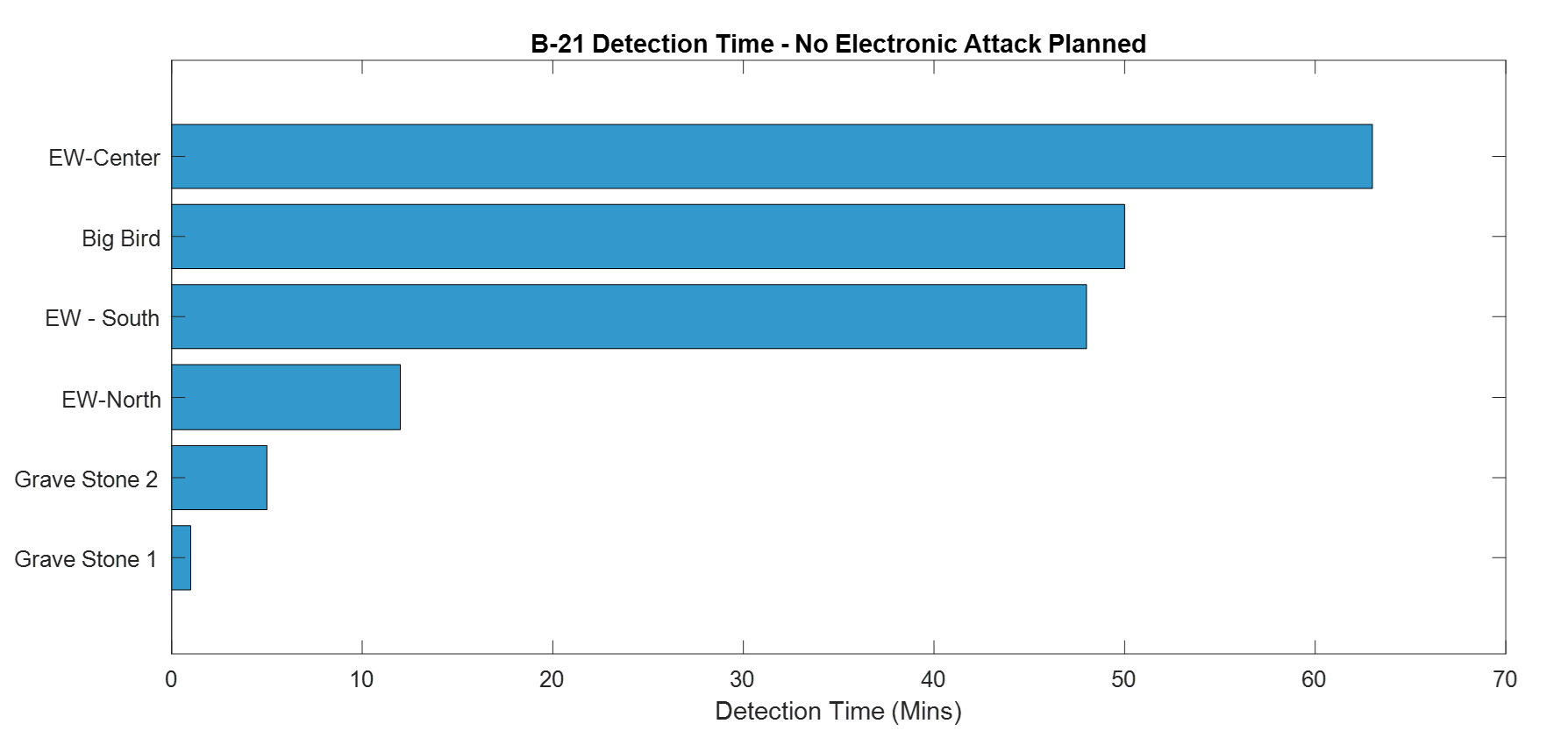
Fig. 3. Baseline detection exposure chart (no jamming): B-21 detection time against each IADS element — EW-Center (63 min) and Big Bird (51 min) dominate total exposure.
EW-Center leads at roughly 63 minutes, followed closely by Big Bird at 51 minutes and EW-South at 49 minutes. These three systems account for the overwhelming majority of total detection exposure. The two Gravestone sites barely register, with Gravestone 2 at about 6 minutes and Gravestone 1 under 2 minutes.
Here’s where the first planning mistake happens. The natural instinct is to point at EW-Center and say “that’s our biggest problem, jam that first.” That instinct is partially right, but incomplete. Detection time tells you where exposure lives. It does not tell you what to jam first.
Lethality comes before leverage. The Gravestones have tiny bars, but they are SAM systems. If either Gravestone acquires and tracks the B-21, we are no longer talking about detection time. Our ALR, which we will define later in this chapter, does not allow that outcome. So before we address any high-detection emitter, the Gravestones get suppressed. That is a constraint, not a tradeoff.
Now look at the figure below. EW-Center is knocked down to roughly 7 minutes. EW-South is similarly suppressed. EW-North, Gravestone 1, and Gravestone 2 all show the lightning bolt symbol indicating effective jamming. The plan has worked well across most of the IADS. Except for one system. Big Bird is sitting at the same bar length it had in the baseline, approximately 50 minutes, completely unaffected. The arrow in the figure is asking the most important question in the planning process: what else can we do?
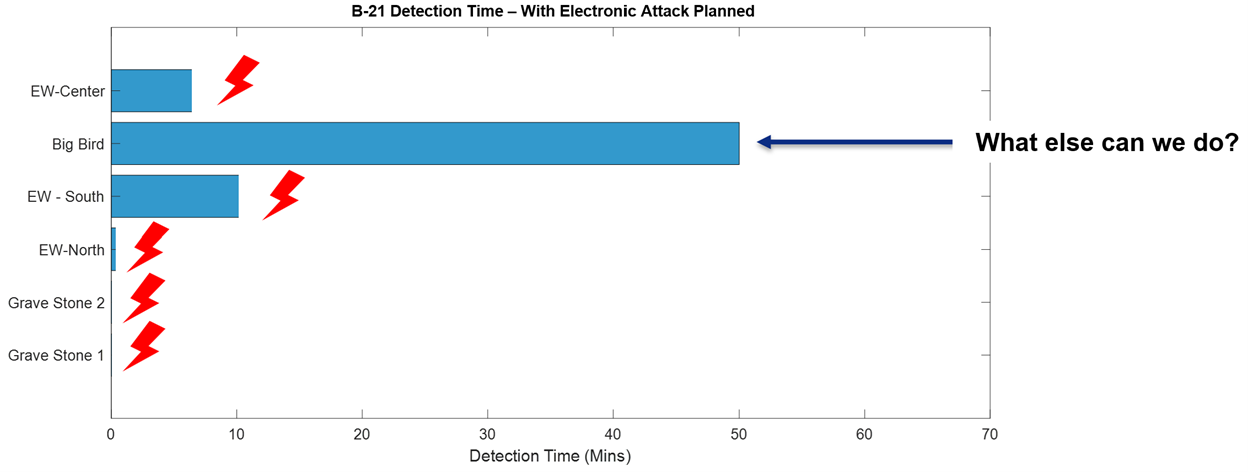
Fig. 4. Detection exposure after jamming plan: EW-Center and EW-South suppressed, Gravestones neutralized — but Big Bird remains at ~50 minutes, indicating residual risk requiring cyber effects.
This reflects a real constraint. Between suppressing the Gravestones for lethality and driving down EW-Center and EW-South for detection leverage, the available electronic attack resources are spoken for. Big Bird remains a problem that jamming alone cannot solve here. That answer lives later in this chapter in the cyber discussion, where we will see how effects delivered through the network rather than the electromagnetic spectrum can reach threats that electronic attack cannot. For now, recognize that what remains after your best jamming plan is executed defines your true residual risk, and that feeds directly into the ALR determination ahead.
Acceptable Level of Detection (ALD)#
Definition#
Acceptable Level of Detection (ALD)
ALD is the threshold at which a mission can tolerate being detected by the adversary without unacceptable degradation of mission success, survivability, or operational value.
Detection is not always equally bad. For some missions, any detection is unacceptable. For others, brief detection may be tolerable if the platform can still accomplish the objective and exit safely.
What ALD Depends On#
ALD is not a fixed universal constant. It is set by the mission planner based on:
Mission type (ISR collection vs. kinetic strike vs. suppression)
Threat environment (presence of long-range SAMs, interceptors, etc.)
Desired operational effect
Platform survivability characteristics
Time sensitivity
Commander’s intent
How ALD Can Be Expressed#
ALD thresholds may be expressed as:
RCS threshold (in dBsm)
Signal-to-noise ratio (SNR) threshold at the threat receiver
Detection range threshold (km)
Time detected (seconds of exposure)
Probability of detection (\(P_D\)) at a specified threshold
ALD Framework#
ALD Level |
Description |
|---|---|
LOW |
Detection is not tolerated. Models shall use \(P_D\) = 90% as the threshold of concern. |
MEDIUM |
Detection for up to two minutes is acceptable. Models shall use \(P_D\) = 50% as the threshold of concern. |
HIGH |
Detection is authorized. |
Critical interpretation: A “HIGH” ALD does not mean the mission is low risk. It means the commander is willing to accept more detection in order to accomplish the mission. Do not confuse ALD level with overall mission safety.
Pre-Strike and Post-Strike ISR#
One of the most ALD-sensitive mission types is Intelligence, Surveillance, and Reconnaissance (ISR) conducted before or after a strike. Objectives may include:
Identifying priority targets
Geolocating emitters and updating the Electronic Order of Battle (EOB)
Observing radar behavior over time (pattern-of-life)
Providing fresh threat data to mission planners
Example: A planner may determine that a specific radar operating at 120 MHz is active approximately 95% of the time. This pattern-of-life data directly informs route planning, jamming timing, and suppression decisions.
Why Airborne ISR Can Outperform Space-Based Collection#
Space-based ELINT and SAR assets are powerful but have a critical limitation: orbital paths are predictable. A sophisticated adversary that understands those orbital mechanics may reduce emissions or alter procedures during known collection windows.
An airborne platform operating below the adversary’s detection threshold may capture emitter behavior under more realistic conditions — an unwarned adversary behaves more naturally, producing higher-quality intelligence. This is why ALD matters for ISR: if the collection platform is detected, the adversary changes behavior, and the intelligence value of the mission degrades sharply.
Acceptable Level of Risk (ALR)#
Definition#
Acceptable Level of Risk (ALR)
ALR is the predefined threshold of potential loss or mission degradation that a commander is willing to tolerate in order to achieve operational objectives.
Where ALD asks “can the enemy see us?”, ALR asks the harder follow-on question: “even if they can, how much damage can we afford to absorb on the way in?”
What ALR Depends On#
ALR balances:
Value and criticality of the mission
Severity of the threat environment
Likelihood of loss
Available resources and replacement capacity
Follow-on mission requirements
How ALR Can Be Expressed#
Probability of aircraft loss (\(P_{loss}\))
Probability of mission failure
Number of platforms expected to be at risk
Attrition constraints (e.g., “no more than 2 aircraft lost”)
Operational degradation limits
ALR Framework#
ALR Level |
Description |
|---|---|
LOW |
Aircraft losses are not acceptable during ingress. SA-5 systems must be degraded. Do not continue with a pop-up threat. |
MEDIUM |
Accept no more than 10% probability of aircraft loss during ingress. Do not continue with a pop-up threat. |
HIGH |
Accept no more than 50% probability of aircraft loss during ingress. |
ALD vs. ALR: The Critical Distinction#
Concept |
Measures |
Question It Answers |
|---|---|---|
ALD |
Tolerated detection |
How much can the enemy see us? |
ALR |
Tolerated loss or mission damage |
How much can we afford to lose? |
These are related but not the same. A mission may tolerate significant detection while still requiring very low aircraft loss probability. For example: a large strike package may accept moderate detection because the force has sufficient jamming and defensive capability to survive even when detected.
Using ALD and ALR Together in Mission Planning#
In real mission planning, ALD and ALR must be considered jointly. Consider these illustrative combinations:
Scenario |
ALD |
ALR |
Rationale |
|---|---|---|---|
Stealth ISR collection |
LOW |
MEDIUM |
Detection ends the mission; loss is bad but secondary concern |
Large strike package |
MEDIUM |
LOW |
Force can survive detection; aircraft loss is politically/operationally unacceptable |
High-priority wartime strike |
HIGH |
HIGH |
Target value justifies accepting both detection and attrition risk |
When selecting jamming priorities, ingress routes, timing, and weapon support, planners must answer two separate questions:
How much detection can we tolerate? → ALD
How much loss can we tolerate? → ALR
These are not interchangeable.
Introduction to Operational Cyber#
“The mission of the United States Air Force is to fly, fight, and win… in air, space and cyberspace.” — United States Air Force Official Website, 2011
Cyberspace is the only warfighting domain in the Air Force’s mission statement that resists a clean, intuitive definition.
Cyberspace (DoD Definition)
Cyberspace: “A domain characterized by the use of electronics and the electromagnetic spectrum to store, modify, and exchange data via networked systems and associated physical infrastructures.”
— 2006 National Military Strategy for Cyberspace Operations
Cyberspace Is Not Just the Internet#
When most people hear “cyber,” they think of internet hacking. That is an important part of the domain — but only one part. Cyberspace includes:
Internet-connected computer networks
Military tactical data links
Industrial control systems (SCADA)
Power grids, water treatment systems, manufacturing facilities
The physical hardware and infrastructure that supports all of the above
Much of the nation’s critical infrastructure is monitored and controlled electronically. Modern electrical grids, hydroelectric dams, nuclear plants, and water treatment facilities are all networked in some form. This means they are all potentially vulnerable to cyber attack. The consequences are not abstract — mass blackouts, industrial explosions, and contaminated water supplies are realistic potential outcomes.
Electronic Attack as Cyber#
Electronic Attack (EA) is formally considered a cyber attack within the DoD framework. Examples include:
Communications jamming: Degrading the data link between tactical assets, impairing blue force coordination
RADAR jamming: Preventing detection, or forcing a radar to “see” something entirely different
Digital Radio Frequency Memory (DRFM): A sophisticated technique in which a device intercepts a radar signal, manipulates it, and re-transmits. Effects include:
Injection of false targets
Shifting the apparent location of a real target
Altering apparent target characteristics
All of this accomplished in near-real-time, often without detection
Electromagnetic Pulse (EMP) as Cyber#
An Electromagnetic Pulse (EMP) is a brute-force method of destroying computing hardware and associated infrastructure. Because it targets the physical layer of digital systems, it is classified within the cyber domain.
The Air Force Research Lab (AFRL) developed the Counter-electronics High-powered Microwave Advanced Missile Project (CHAMP) — a system capable of targeting specific facilities and completely disabling computers and networking equipment. Many military systems are EMP-hardened specifically because of this threat vector.
Cyber Warfare vs. Traditional Warfare#
Cyber operations differ from traditional physical warfare in several important ways. Understanding these differences is essential for planning, attribution, and response. Keep these contrasts in mind as you evaluate how cyber tools fit — or don’t fit — into the mission planning frameworks you’ve already seen.
Category |
Traditional Warfare |
Cyber Warfare |
|---|---|---|
Cost |
Extremely expensive: personnel, training, equipment, logistics |
Often lower cost to initiate effects; requires computers and skilled operators |
Boundaries |
Physical geography clearly defines battlespace |
Effects may originate from anywhere on Earth (or space); no physical borders |
Anonymity |
Attacker is typically identifiable |
Sophisticated attackers can cover tracks; victim may never identify origin |
Attribution |
Usually straightforward: you see who crossed the border |
IP addresses and system identities may be spoofed; attribution may be wrong |
Sovereignty |
Territorial sovereignty provides a clear framework for response |
Ownership of cyberspace is murky; response thresholds are legally and politically ambiguous |
The Attribution Problem#
In conventional warfare, if a nation’s tank crosses your border, you know who sent it. In cyberspace:
IP addresses can be spoofed or routed through proxy systems
Attacks may be launched from compromised third-party systems (not the true origin)
Sophisticated state-level actors may deliberately mimic other nations’ techniques (false flag operations)
This creates a strategic dilemma. If you are attacked through cyberspace, the questions “who did it,” “from where,” and “at what threshold should we respond” are far harder to answer than in conventional warfare.
Important caveat: Cyber operations are not cheap or easy. Sophisticated effects require expertise, intelligence, access development, and preparation — often over months or years. The “low cost” relative to conventional forces should not imply that cyber is consequence-free or trivially executed.
Key Cybersecurity Concepts: The CIA Triad#
The CIA Triad
The DoD’s cybersecurity posture is organized around three core properties:
Confidentiality — Only authorized individuals may access information.
Integrity — Unauthorized modification of data is prevented.
Availability — Data is accessible to the right person at the right time.
Confidentiality#
Only authorized individuals may access information. Methods to enforce confidentiality:
Physical or logical network separation (air-gapping classified networks)
Multi-factor authentication (MFA) (e.g., CAC + PIN)
Encryption: Mathematical scrambling using an algorithm and key, rendering data unreadable without the key — even if intercepted
Integrity#
Preventing unauthorized modification of data. In an IADS context, integrity is arguably the most dangerous property to lose: a radar that is shut down is obviously broken, but a radar that quietly reports false tracks may go undetected while causing the C2 system to make catastrophically wrong decisions. Methods:
Role-based / permission-based access control: Users may be granted read-only access, preventing modification even by authenticated users
Encryption of data at rest: Protects against undetected tampering
Audit logging: Records changes for forensic analysis
If an adversary can silently modify the data in your C2 system — injecting false tracks, altering engagement assignments, corrupting status displays — the damage may be far worse than a system shutdown. At least a shutdown is immediately visible.
Availability#
Data is useless if it cannot be accessed by the right person at the right time. For a time-critical system like an IADS, even a brief interruption in data availability can break the kill chain just as effectively as destroying a radar — which is why Denial-of-Service attacks against C2 networks can have outsized operational impact. Availability focuses on:
Hardware reliability and redundancy
Backup and recovery systems for catastrophic data loss
Communication bandwidth adequate to move data to users
Physical and cyber protection of hardware from attack
Common controls: firewalls, secure routers, encrypted communication lines, network monitoring software.
The CIA Trade-Off#
The most secure system in the world is a stand-alone computer, powered off, locked in a vault, with no network connections. It has perfect confidentiality and perfect integrity. It also has zero availability and is therefore completely useless. All real systems require balancing the three properties.
System |
Confidentiality |
Integrity |
Availability |
Rationale |
|---|---|---|---|---|
Combat ID / C2 system |
HIGH |
HIGH |
HIGH |
All three critical; requires expensive implementation |
Utility metering relay |
LOW |
HIGH |
HIGH |
Accuracy and real-time response critical; data visibility not sensitive |
Classified planning database |
HIGH |
HIGH |
MEDIUM |
Authorized-only access; can tolerate some latency |
Encryption in Practice#
Encryption uses a mathematical algorithm and a key to transform plaintext data into ciphertext:
Plaintext + Key + Algorithm  ──►  Ciphertext
                                      │
                           (unreadable to anyone without key)
Even if an adversary intercepts the ciphertext, without the key they cannot recover the original information. Encryption protects both confidentiality (hiding content) and integrity (detecting tampering).
Cyber Threat Vectors#
If planners want to protect or exploit a networked IADS, they must understand how cyber access is gained.
Network Hacking#
Access through internet-connected or otherwise network-accessible systems. Common enablers:
Misconfigurations (open ports, default credentials)
Exposed services with known vulnerabilities
Weak or reused passwords
Unpatched software
Once initial access is gained, an attacker typically attempts to:
Move laterally to other systems in the network
Escalate privileges to gain administrative access
Establish persistence (maintain access even if discovered)
Exfiltrate, manipulate, or destroy target data or functions
Physical Access#
Not all cyber compromise begins remotely. Physical access can be extremely powerful — and may be the only viable path into air-gapped networks.
Examples:
Malicious or compromised removable media (USB drives)
Maintenance laptops with pre-installed malware
Compromised hardware components introduced during maintenance
An “air-gapped” network (one with no external internet connection) is not automatically safe. Physical insertion bypasses the network entirely. The most famous example is the Stuxnet worm, which is believed to have reached air-gapped Iranian nuclear facilities via infected USB drives.
Supply Chain Threats#
Compromise can occur before the system is ever fielded. Malicious hardware, firmware, or software may be introduced during:
Manufacturing
Transport / logistics
System integration
Maintenance and depot repair
Supply chain threats are especially dangerous because the compromise may remain dormant — undetectable during normal operation — until activated under specific conditions (such as deployment to a specific operational location or receipt of a trigger signal).
Summary of Vectors#
Vector |
Entry Point |
Key Risk |
|---|---|---|
Network hacking |
Remote, via internet or tactical network |
Stealthy lateral movement |
Physical access |
On-site insertion of malicious media or hardware |
Bypasses all network-layer defenses |
Supply chain |
Pre-deployment, during manufacture or maintenance |
May be undetectable until triggered |
Cybersecurity is not just about firewalls. It includes people, processes, hardware trust, software assurance, and operational discipline at every phase of the system lifecycle.
Understanding how adversaries gain access is only half the picture — the other half is knowing how to deliberately apply cyber effects as a planning tool against an IADS.
Cyber Operations Planning Considerations#
Cyber capabilities are valuable, but they require careful, deliberate planning. Key considerations:
Aligning actions to the phase of conflict (peacetime shaping vs. active hostilities)
Weighing near-term gain against long-term consequences (using a capability may reveal it)
Preserving access and tools when possible — a cyber capability is often a one-time use
Avoiding unnecessary exposure of techniques
Observable vs. Obfuscated Effects#
One of the most important planning decisions is whether the intended effect should be observable or obfuscated.
Observable Effects#
The target clearly perceives the attack. Examples:
Radar suddenly stops functioning
Displays go blank
Network obviously fails
Advantage: Immediate, demonstrable disruption. Disadvantage: Alerts the adversary that an attack is underway, prompting recovery and reconfiguration.
Obfuscated Effects#
The attack is designed to mislead or degrade without revealing that a compromise is underway. Examples:
Subtle corruption of track data
Slightly delayed or inaccurate correlations
Altered target status information
False engagement assessment data
Advantage: Adversary continues operating on bad data; access may be preserved for future use. Disadvantage: Effect may be slower or less immediately dramatic.
Observable effects are like cutting a wire — immediately obvious and promptly repaired. Obfuscated effects are like adding a small but growing resistance to that same wire — the system degrades gradually, the fault is hard to localize, and the adversary may not realize what’s happening until significant damage has occurred.
IADS-Specific Cyber Planning Questions#
Applied to an IADS, cyber planners may ask:
Should we shut down the radar entirely, or corrupt its track data?
Should we interfere with data links, or only with the C2 fusion function?
Should we remove information from the C2 system, or alter it?
Should we target seeker support software or weapons coordination systems?
The best answer depends on the specific mission objective. Sometimes obvious disruption is desired. Other times, deception is more valuable than destruction.
Radar Cross Section and Polar Plots#
Earlier in this course you encountered RCS as a single scalar value inserted into the RADAR equation. That single-number model is a useful starting point, but it hides something operationally critical: RCS is not a single fixed number — it changes with the geometry between the platform and the radar. Detectability is strongly dependent on aspect angle and aircraft configuration.
RCS Polar Plots#
An RCS polar plot shows how the apparent radar cross section (in dBsm) varies as the radar observes the platform from different azimuth or elevation angles. A platform may present a very small RCS from the front (nose-on) and a much larger RCS from the side (beam aspect).
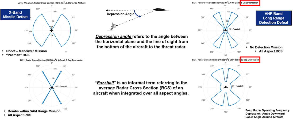
Fig. 5. RCS polar plot: radar cross section (dBsm) as a function of azimuth angle — nose-on aspect shows minimum RCS while beam aspect shows maximum RCS.
Depression Angle#
Depression angle is the angle between the horizontal plane and the line-of-sight from the aircraft down to the threat radar.
                Aircraft
                   │
                   │  ← Depression Angle (θ)
                   │
       ────────────┤────────────  Horizontal Plane
                   │
                 Radar
As the geometry changes — due to aircraft altitude, range, or radar placement — different surface features of the aircraft are illuminated, changing the apparent RCS. A mission that takes the aircraft at high altitude over a threat radar may present a very different (and potentially much larger) RCS than a low-altitude ingress geometry.
“Fuzzball” RCS and Its Limitations#
An informal metric sometimes used in preliminary analysis is the fuzzball RCS — the average RCS of an aircraft when integrated over all aspect angles. This can be useful as a quick summary figure of merit.
However, mission success depends on the specific aspects encountered during the mission, not the average. A platform with a favorable mean RCS may still be critically vulnerable if a particular route segment exposes a much larger aspect angle to a key threat radar at exactly the wrong moment.
Practical implication: Route planning must account for aspect angle relative to each significant threat emitter along the entire ingress and egress.
Putting It All Together#
An IADS is a layered, networked combat system that relies on sensors, communication links, C2 nodes, and weapons working together. Mission planning against an IADS is therefore a systems engineering problem, not a single-radar problem.
The Survivability Design Space#
To survive and succeed, planners combine tools across multiple layers:
Layer |
Tools Available |
|---|---|
Detection reduction |
LO design, geometry management, altitude management, EMCON |
Track denial |
RCS shaping, jamming, maneuver |
C2 degradation |
Cyber operations, kinetic strike, link denial |
Weapon defeat |
Decoys, active defenses, maneuver |
The Decision Framework#
Commanders and planners use ALD and ALR to structure every decision:
MISSION OBJECTIVE
        │
        ▼
Set ALD ──────────────────────── How much detection can we tolerate?
        │
        ▼
Set ALR ──────────────────────── How much loss can we tolerate?
        │
        ▼
Design: ISR plan, routes, jamming priorities, cyber actions, weapons support
        │
        ▼
Execute and Assess
Cyber as a Dimension of the Problem#
Because modern IADS architectures are digital and networked, cyberspace is central to both the defense and the offense. Cyber operations may:
Degrade radars (observable or obfuscated)
Corrupt track data
Break or manipulate communication links
Alter C2 system data
Preserve operational surprise
But those actions must be weighed carefully — particularly if preserving access for future operations is a priority.
Key Takeaways#
An IADS is a networked combination of sensors, communications, C2, and weapons. Its power derives from integration and data sharing.
The best survivability strategy is to break the kill chain as early as possible.
ALD measures tolerated detection; ALR measures tolerated loss or mission degradation. They are related but distinct.
Jammer tuning and threat prioritization must reflect mission objectives, ALD, and ALR. Use Pareto thinking.
Cyber operations can target radars, links, C2 nodes, or data integrity — with observable or obfuscated effects. Choose deliberately.
RCS is aspect-dependent. A single average RCS value is insufficient for mission planning. Geometry matters.
The CIA Triad (Confidentiality, Integrity, Availability) governs cybersecurity design, and all three properties must be balanced against mission requirements and cost.
Cyber threats enter through networks, physical access, and supply chains. Firewalls alone are not sufficient.