Lesson 15 - Boolean Algebra for Digital Logic Analysis#
Lesson Objectives#
Express logic gates as Boolean equations.
Construct truth tables from Boolean equations and logic diagrams.
Develop Boolean equations from truth tables.
Simplify Boolean equations using Boolean algebra identities.
Apply Boolean algebra to design and analyze logic circuits.
15.1 From Transistor Networks to Boolean Expressions#
In the previous lesson, we examined how transistors are used to implement digital logic functions. Specifically, we studied how transistor configurations in series and parallel, as well as the location from which the output voltage is measured, determine the logical behavior of a circuit.:
Series conduction requires all devices to conduct → AND behavior.
Parallel conduction requires any one device to conduct → OR behavior.
Inversion occurs when the output is taken at a complementary node → NOT behavior.
In this lesson, we transition from the physical transistor implementation to its mathematical representation using Boolean algebra. Boolean equations allow us to represent logic gates symbolically and analyze their behavior using algebraic rules.
Boolean equations serve several critical engineering purposes:
They allow us to construct truth tables directly from equations.
They allow us to draw logic diagrams from algebraic expressions.
They enable systematic simplification of circuits to minimize gate count.
They allow us to compute output behavior without referencing the physical schematic.
15.2 Logic Gates as Boolean Equations#
Figure 15.1 summarizes the three foundational logic operators.
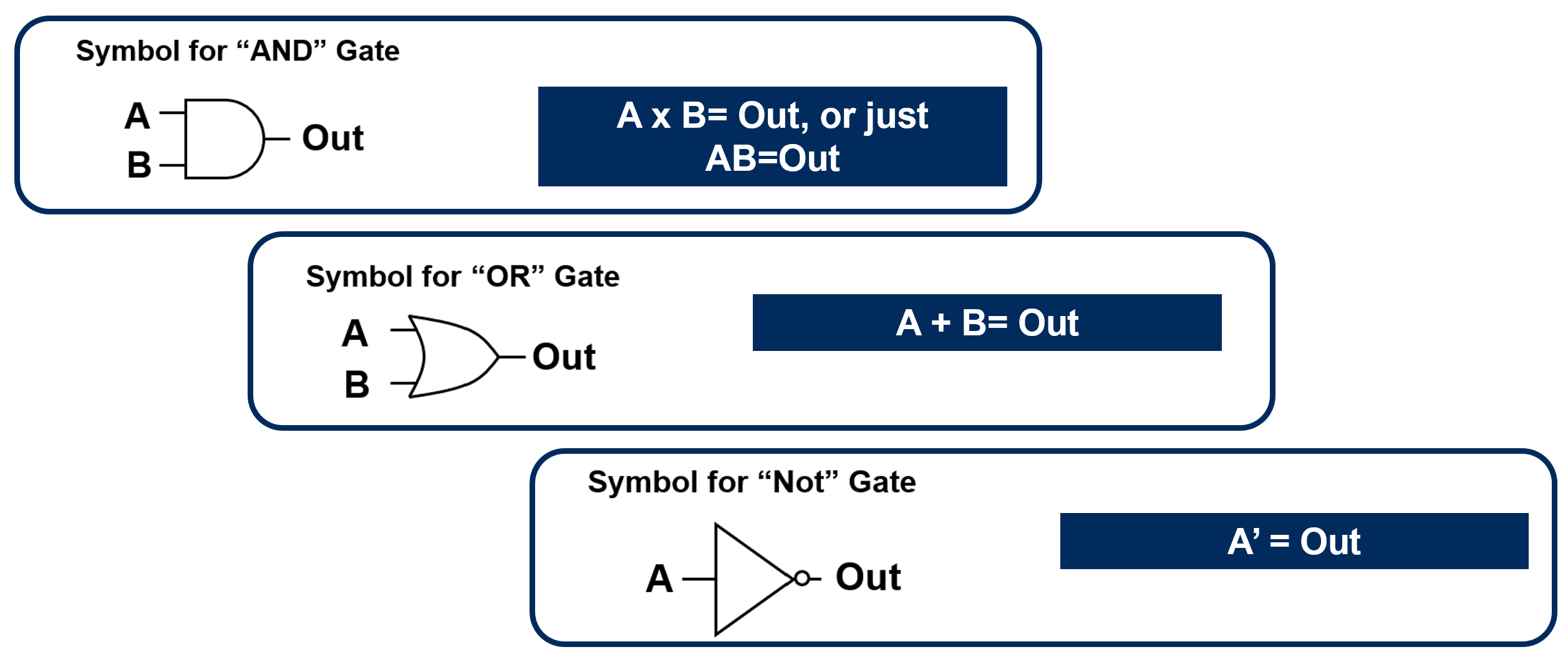
AND Gate#
The AND gate outputs 1 only when both inputs are 1.
In compact form (common in ECE 315):
This multiplication operator reflects the series conduction requirement: the output is 1 only when both
OR Gate#
The OR gate outputs 1 when at least one input is 1.
The addition symbol reflects the parallel conduction path: only one input must be true for the output to be true.
NOT Gate#
The NOT gate inverts its input.
The NOT operation is fundamental because it allows us to construct complementary logic conditions and is essential for algebraic simplification in later sections. With these symbolic representations established, we can now move systematically between physical circuits, Boolean equations, and truth tables, forming the foundation for rigorous digital logic analysis and design.
15.3 Boolean Arithmetic#
Boolean arithmetic is not base-10 arithmetic. The operators are defined over \(\{0,1\}\).
AND (Multiplication)#
Interpretation:
True AND False = False
True AND True = True
OR (Addition)#
Important: \(1+1=1\) (not 2). Boolean outputs can only be 0 or 1.
NOT (Complement)#
15.4 From Logic Diagram to Boolean Equation#
Example 1: Convert a Logic Diagram to an Equation#
Figure 15.2 shows a two-input logic diagram. Your task is to write its Boolean equation.
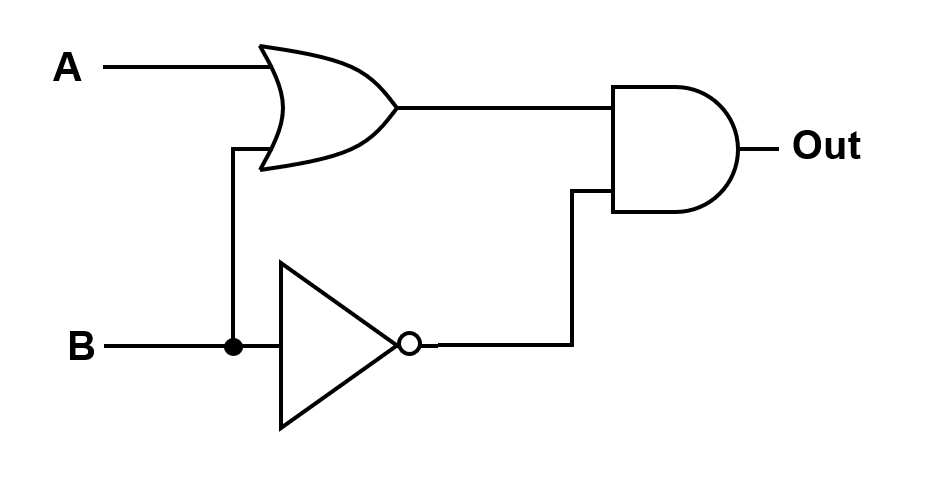
Step 1 — Identify each gate output#
The first gate is an OR receiving \(A\) and \(B\), so its output is \((A+B)\).
The lower branch inverts \(B\), producing \(B'\).
Step 2 — Combine at the final gate#
The final gate is an AND, so multiply the two signals:
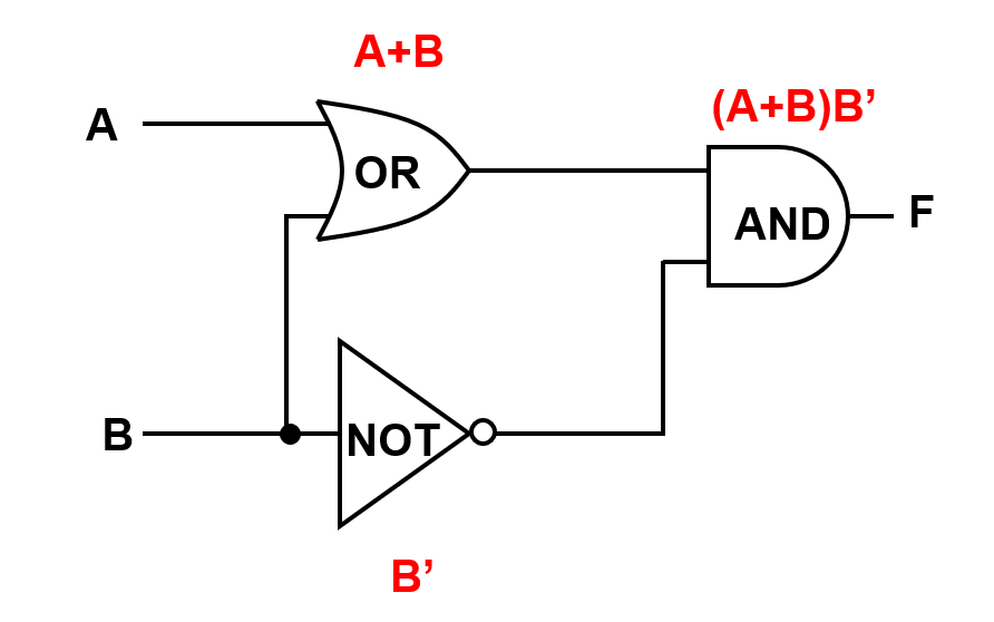
Figure 15.3 shows the same circuit annotated with intermediate expressions.
15.5 From Boolean Equation to Truth Table#
Boolean equations can be evaluated row-by-row to create truth tables.
Example 2: Build a Truth Table from an Equation#
Given:
Evaluate for all combinations of \(A\) and \(B\). A clean way to execute this is:
Compute \((A+B)\)
Compute \((A+B')\)
Multiply the results
\(A\) |
\(B\) |
\((A+B)\) |
\((A+B')\) |
\(\text{Out}=(A+B)(A+B')\) |
|---|---|---|---|---|
0 |
0 |
0 |
1 |
0 |
0 |
1 |
1 |
0 |
0 |
1 |
0 |
1 |
1 |
1 |
1 |
1 |
1 |
1 |
1 |
This example highlights a common Boolean rule: even though \(1+1\) would be 2 in base-10 arithmetic, in Boolean algebra it remains 1.
15.6 From Truth Table to Boolean Equation (Sum of Products)#
A standard method for converting a truth table to an equation is the Sum of Products (SOP) form.
SOP Procedure#
Identify all rows where the output equals 1.
For each such row, write a product (AND) term using all input variables:
If an input is 0, use the complemented variable (e.g., \(A'\)).
If an input is 1, use the uncomplemented variable (e.g., \(A\)).
OR (sum) all product terms together.
This guarantees a correct expression, though it may not be minimal.
Example 3: SOP with Two Inputs#
\(A\) |
\(B\) |
\(F\) |
|---|---|---|
0 |
0 |
1 |
0 |
1 |
0 |
1 |
0 |
1 |
1 |
1 |
0 |
Rows where \(F=1\):
\((A,B)=(0,0)\) → \(A'B'\)
\((A,B)=(1,0)\) → \(AB'\)
Therefore:
At this point you may simplify (Section 15.8).
Example 4: SOP with Two Inputs (Three Ones)#
\(A\) |
\(B\) |
\(F\) |
|---|---|---|
0 |
0 |
0 |
0 |
1 |
1 |
1 |
0 |
1 |
1 |
1 |
1 |
Rows where \(F=1\):
\((0,1)\) → \(A'B\)
\((1,0)\) → \(AB'\)
\((1,1)\) → \(AB\)
So:
15.7 Boolean Identities#
Boolean identities allow you to simplify expressions systematically.
# |
Identity |
|---|---|
1 |
\(A+0=A\) |
2 |
\(A+1=1\) |
3 |
\(A+A=A\) |
4 |
\(A+A'=1\) |
5 |
\(A\cdot 0=0\) |
6 |
\(A\cdot 1=A\) |
7 |
\(A\cdot A=A\) |
8 |
\(A\cdot A'=0\) |
9a |
\(A(B+C)=AB+AC\) |
9b |
\(A+BC=(A+B)(A+C)\) |
10a |
\((A+B)'=A'B'\) |
10b |
\((AB)'=A'+B'\) |
11a |
\(A+AB=A\) |
11b |
\(AB+AB'=A\) |
Two identities that frequently reduce transistor/gate count immediately are:
Identity 4: \(A+A'=1\) (complements through OR collapse to 1)
Identity 8: \(A\cdot A'=0\) (complements through AND collapse to 0)
15.8 Simplifying Boolean Equations (Worked Examples)#
Example 4 Simplification (From Section 15.6)#
Start with:
Step 1 — Factor using distributive property (Identity 9a)#
Group the last two terms:
Step 2 — Apply complement rule (Identity 4)#
So:
Step 3 — Apply identity (Identity 6)#
So:
Step 4 — Apply identity (9b)#
Step 5 — Apply identity (4)#
Step 6 — Substitute into the original expression:#
Step 7 - Apply identity (6)#
Therefore,
Interpretation: The original three-term SOP truth table implements a single OR gate.
15.9 Diagram → Equation → Simplification → Truth Table#
Figure 15.3 already provides a direct equation for the diagram:
Distribute (Identity 9a):
Apply Identity 8:
So:
Truth table for \(F=AB'\):
\(A\) |
\(B\) |
\(F\) |
|---|---|---|
0 |
0 |
0 |
0 |
1 |
0 |
1 |
0 |
1 |
1 |
1 |
0 |
Design takeaway: An algebraic simplification can eliminate entire gates, reducing cost, power, and delay.
15.10 Three-Input Design (Truth Table → SOP → Simplification)#
When the number of inputs increases, the SOP method remains valid. It may produce a large initial expression, but identities can often reduce it substantially.
Example 6: Three Inputs#
The truth table below is a representative three-input design task:
\(A\) |
\(B\) |
\(C\) |
\(\text{Out}\) |
|---|---|---|---|
0 |
0 |
0 |
1 |
0 |
0 |
1 |
0 |
0 |
1 |
0 |
0 |
0 |
1 |
1 |
0 |
1 |
0 |
0 |
1 |
1 |
0 |
1 |
0 |
1 |
1 |
0 |
0 |
1 |
1 |
1 |
1 |
SOP Construction#
Rows where \(\text{Out}=1\):
\((0,0,0)\) → \(A'B'C'\)
\((1,0,0)\) → \(AB'C'\)
\((1,1,1)\) → \(ABC\)
So:
Simplification#
Factor the first two terms by \(B'C'\):
Apply Identity 4:
So:
Apply Identity 10a (DeMorgan’s Law):
Substitute into the original expression:
Why This Reduces the Transistor Count (4 → 3)#
Using Only AND / OR / NOT#
Consider the two equivalent forms:
and
Although they are algebraically identical (by DeMorgan’s Law), their hardware implementations differ.
Implementation 1 — \(B'C'\)#
This form is constructed as:
NOT gate on \(B\) → produces \(B'\)
NOT gate on \(C\) → produces \(C'\)
AND gate combining \(B'\) and \(C'\) → produces \(B'C'\)
This requires:
Three (3) logic gates
Four (4) transistors in the effective series/parallel network
Implementation 2 — \((B + C)'\)#
This form is constructed as:
OR gate to compute \((B + C)\)
NOT gate to invert the result
This requires:
Two (2) logic gates
Three (3) transistors in the effective series/parallel network
Engineering Conclusion#
By applying DeMorgan’s Law:
we reduce:
The number of logic gates
The effective transistor count (from 4 to 3)
This is a direct example of how Boolean algebra enables hardware optimization without changing functional behavior.
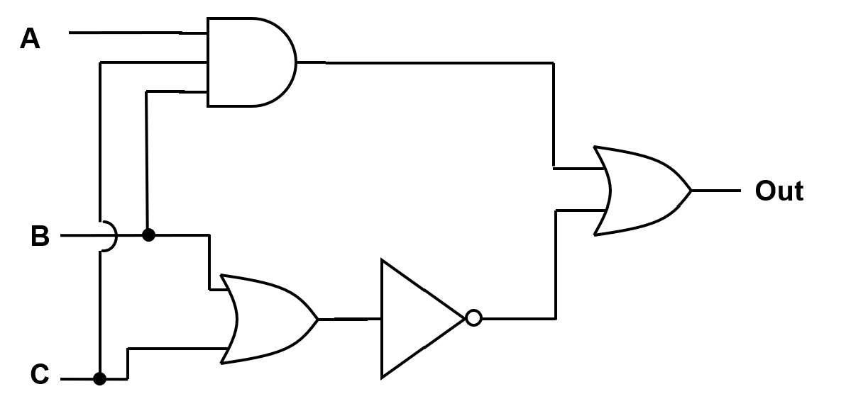
Figure 15.4 shows a three-input logic diagram structure used in multi-input analysis and practice.
15.11 Standard Workflow Summary#
Given a Logic Diagram#
Write the Boolean expression gate-by-gate.
Simplify with Boolean identities.
Build the truth table from the simplified equation.
Given a Truth Table#
Construct SOP from every row where output = 1.
Simplify using Boolean identities.
Draw the minimized logic diagram.
15.12 Why Simplification Matters#
Simplification reduces:
Gate count
Transistor count
Power consumption
Layout complexity
In engineering terms, Boolean algebra is a design optimization tool: it achieves the same behavior with fewer resources.